Add Sensors
AWSIM Sensors
There is a number of different sensors available in AWSIM. Below we present a list of sensors with links to their individual pages.
Add links for sensors
Best practice is to replicate a ROS sensors transformations tree in Unity using Objects.
Coordinate system conversion
Please note that Unity uses less common left-handed coordinate system. Please keep this in mind while defining transformations. More details about right-handed and left-handed systems can be found here.
To simplify the conversion process always remember that any point in ROS coordinate system (x, y, z) has an equivalent in the Unity coordinate system being (-y, z, x).
The same can be done with the rotation.
ROS orientation described with roll, pitch and yaw (r, p, y) can be translated to Unity Rotation as follows (p, -y, -r).
Unit conversion
Please remember to convert the rotation units.
ROS uses radians and Unity uses degrees.
The conversion from radians (rad) to degrees (deg) is as follows.
deg = rad * 180 / PI
Add transformations tree
URDF
Before following this tutorial please make sure you have an URDF Object like it is shown shown in this section.
First we will have to add a base_link which is the root of all transformations.
Add a base_link Object as a child to the URDF Object.
base_link transformation
Please remember to set an appropriate transformation of the base_link Object so that it is identical as the base_link used in ROS in reference to the Vehicle.
This is very important, as a mistake here will result in all subsequent sensors being misplaced.
Inside the base_link we will represent all transformations contained in the ROS transformations tree.
You will have to check your Vehicle specific configuration. You can do this in many ways, for example:
-
Check the ROS specific
.yamlparameter files containing information about each transformation.Example
Here we see an example
.yamlfile containing transformation from thebase_linkto thesensor_kit_base_link:base_link: sensor_kit_base_link: x: 0.9 y: 0.0 z: 2.0 roll: -0.001 pitch: 0.015 yaw: -0.0364 -
Check the values with ROS command line tools (for more information on these please visit official ROS 2 documentation).
You can run a command like the following to check a transformation between two frames.
ros2 run tf2_ros tf2_echo [source_frame] [target_frame]Example
Here we see an example command with the output containing transformation from the
base_linkto thesensor_kit_base_link(note that the line after$sign is the executed command):$ ros2 run tf2_ros tf2_echo base_link sensor_kit_base_link [INFO] [1686654712.339110702] [tf2_echo]: Waiting for transform base_link -> sensor_kit_base_link: Invalid frame ID "base_link" passed to canTransform argument target_frame - frame does not exist At time 0.0 - Translation: [0.900, 0.000, 2.000] - Rotation: in Quaternion [-0.000, 0.008, -0.018, 1.000] - Rotation: in RPY (radian) [-0.001, 0.015, -0.036] - Rotation: in RPY (degree) [-0.057, 0.859, -2.086] - Matrix: 0.999 0.036 0.015 0.900 -0.036 0.999 0.000 0.000 -0.015 -0.001 1.000 2.000 0.000 0.000 0.000 1.000
Add one sensor link
Note
In this step we will only add one sensor link. You will have to repeat this step for every sensor you want to add to your Vehicle.
Let's say we want to add a LiDAR that is facing right.
We have the following configuration files.
base_link:
    sensor_kit_base_link:
        x: 0.9
        y: 0.0
        z: 2.0
        roll: -0.001
        pitch: 0.015
        yaw: -0.0364
sensor_kit_base_link:
    velodyne_right_base_link:
        x: 0.0
        y: -0.56362
        z: -0.30555
        roll: -0.01
        pitch: 0.71
        yaw: -1.580
We can clearly see the structure of transformation tree. The transformations are as follows.
base_link -> sensor_kit_base_link -> velodyne_right_base_link
We need to start adding these transformation from the root of the tree.
We will start with the sensor_kit_base_link, as the base_link already exists in our tree.
-
The first step is to add an Object named the same as the transformation frame (
sensor_kit_base_link).
-
Next we have to convert the transformation from ROS standard to the Unity standard. This is done with the formulas show in this section.
The result of conversion of the coordinate systems and units is shown below.
Position:
(0.9, 0.0, 2.0)             ->  (0.0, 2.0, 0.9)
Rotation:
(-0.001, 0.015, -0.0364)    ->  (0.8594, 2.0856, 0.0573)
The resulting
sensor_kit_base_linkObject transformation is shown below.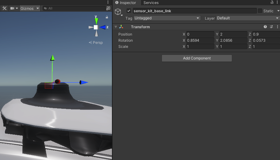
Now the same has to be done with the velodyne_right_base_link.
-
Add transformation Object (
velodyne_right_base_link).Info
Remember to correctly set the child Object, in this case we use
sensor_kit_base_linkas a child, because this is what the.yamlfile says.
-
Convert the transformation into Unity coordinate system.
The correct transformation is shown below.
Position:
(0, -0.56362, -0.30555)     ->  (0.56362, -0.30555, 0)
Rotation:
(-0.01, 0.71, -1.580)       ->  (40.68, 90.5273, 0.573)
The final
velodyne_right_base_linkObject transformation is shown below.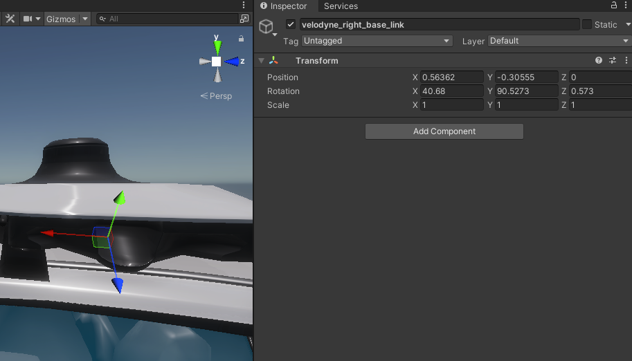
Success
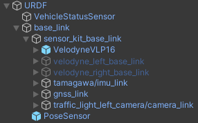
If you have done everything right, after adding all of the sensor links your URDF Object tree should look something like the one following.
Add sensors
After adding links for all sensors you need to add the actual sensors into your Vehicle.
Sensor position
Please keep in mind, that we have created the sensor links in order to have an accurate transformations for all of the sensors. This implies that the Sensor Object itself can not have any transformation.
If one of your Sensors, after adding it to the scene, is mispositioned, check whether the transformation is set to identity (position and rotation are zeros).
When adding sensors almost all of them will have some common fields.
-
Frame Id
Frame Id is the name of frame of reference against which the received data will be interpreted by the autonomous driving software stack.
Remember that the Frame Id must exist internally in the ROS transformations tree.
-
Topics
Topics are names of broadcasting channels. You can set the names of topics as you like and the data from sensors will be broadcasted on these topics.
Remember to configure your receiving end to listen on the same topics as broadcasting ones.
-
Quality Of Service settings (QOS settings)
Quality of service settings allow you to configure the behavior of the source node while broadcasting the sensor data. You can adjust these settings to suit your needs.
Add a Vehicle Status Sensor
To add a Vehicle Status Sensor to your Vehicle simply locate the following directory in the Project view and drag a prefab of this Sensor into the URDF Object.
Assets/AWSIM/Prefabs/Sensors
Next in the Inspector View select your Vehicle.
ROS message example
In this example you can see what a valid message from the Vehicle Status Sensor can look like.
$ ros2 topic echo --once /vehicle/status/velocity_status
header:
  stamp:
    sec: 17
    nanosec: 709999604
  frame_id: base_link
longitudinal_velocity: 0.004912620410323143
lateral_velocity: -0.005416259169578552
heading_rate: 0.006338323466479778
---
Add a LiDAR
Scene Manager
Before continuing with this tutorial please check out a dedicated one focused on Scene Manager.
To add a LiDAR to your Vehicle you will have to drag a model of the LiDAR to the link tree you have created in the earlier step.
You can use the predefined RGL LiDAR models or any other LiDAR models.
In this tutorial we will be using RGL VelodyneVLP16 LiDAR model.
Simply locate the following directory in the Project view and drag the prefab into the designated sensor link.
Assets/AWSIM/Prefabs/Sensors/RobotecGPULidars
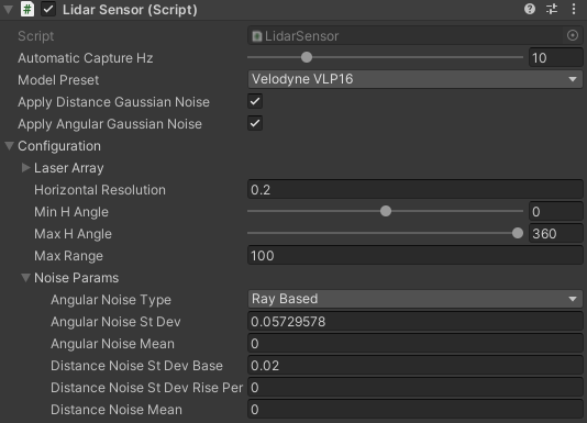
LiDAR noise configuration
LiDAR Sensor in simulation is returning a perfect result data. This is not an accurate representation of the real-world.
LiDAR Sensor addresses this issue by applying a simulated noise to the output data.
You can configure the noise parameters in the Inspector View under Configuration -> Noise Params fields.
You can optionally remove the noise simulation by unchecking the Apply Distance/Angular Gaussian Noise.
You can also change the ranges of the LiDAR detection.
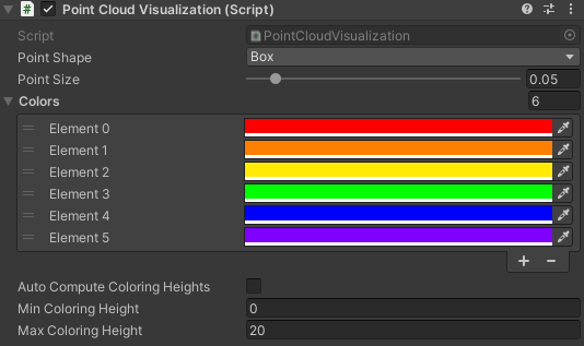
There is also a possibility to configure the visualization of the Point Cloud generated by the LiDAR. E.g. change the hit-point shape and size.
ROS message example
In this example you can see what a valid message from the LiDAR Sensor can look like.
$ ros2 topic echo --once /lidar/pointcloud
header:
  stamp:
    sec: 20
    nanosec: 589999539
  frame_id: world
height: 1
width: 14603
fields:
- name: x
  offset: 0
  datatype: 7
  count: 1
- name: y
  offset: 4
  datatype: 7
  count: 1
- name: z
  offset: 8
  datatype: 7
  count: 1
- name: intensity
  offset: 16
  datatype: 7
  count: 1
- name: ring
  offset: 20
  datatype: 4
  count: 1
is_bigendian: false
point_step: 24
row_step: 350472
data:
- 156
- 218
- 183
- 62
- 0
- 189
- 167
- 187
- 32
- 58
- 173
- 189
- 0
- 0
- 0
- 0
- 0
- 0
- 200
- 66
- 1
- 0
- 0
- 0
- 198
- 129
- 28
- 63
- 0
- 6
- 230
- 58
- 128
- 184
- 93
- 61
- 0
- 0
- 0
- 0
- 0
- 0
- 200
- 66
- 9
- 0
- 0
- 0
- 92
- 2
- 194
- 62
- 0
- 141
- 42
- 187
- 128
- 89
- 139
- 189
- 0
- 0
- 0
- 0
- 0
- 0
- 200
- 66
- 2
- 0
- 0
- 0
- 187
- 168
- 42
- 63
- 0
- 159
- 175
- 59
- 160
- 243
- 185
- 61
- 0
- 0
- 0
- 0
- 0
- 0
- 200
- 66
- 10
- 0
- 0
- 0
- 119
- 186
- 204
- 62
- 0
- 254
- 23
- 59
- 128
- 143
- 41
- 189
- 0
- 0
- 0
- 0
- 0
- 0
- 200
- 66
- 3
- 0
- 0
- 0
- 65
- 241
- 59
- 63
- 128
- 0
- 252
- 187
- '...'
is_dense: true
---
Add an IMU
To add an IMU to your Vehicle you will have to drag a model of the IMU to the link tree you have created in the earlier step.
You can use the provided or your own IMU Sensor. In this tutorial we will be using IMU Sensor provided with AWSIM.
Simply locate the following directory in the Project view and drag the prefab into the designated sensor link.
Assets/AWSIM/Prefabs/Sensors
ROS message example
In this example you can see what a valid message from the IMU Sensor can look like.
$ ros2 topic echo --once /sensing/imu/tamagawa/imu_raw
header:
  stamp:
    sec: 20
    nanosec: 589999539
  frame_id: tamagawa/imu_link
orientation:
  x: 0.0
  y: 0.0
  z: 0.0
  w: 1.0
orientation_covariance:
- 0.0
- 0.0
- 0.0
- 0.0
- 0.0
- 0.0
- 0.0
- 0.0
- 0.0
angular_velocity:
  x: 0.014335081912577152
  y: 0.008947336114943027
  z: -0.008393825963139534
angular_velocity_covariance:
- 0.0
- 0.0
- 0.0
- 0.0
- 0.0
- 0.0
- 0.0
- 0.0
- 0.0
linear_acceleration:
  x: 0.006333829835057259
  y: -0.005533283110707998
  z: -0.0018753920448943973
linear_acceleration_covariance:
- 0.0
- 0.0
- 0.0
- 0.0
- 0.0
- 0.0
- 0.0
- 0.0
- 0.0
---
Add a GNSS
To add a GNSS Sensor to your Vehicle you will have to drag a model of the GNSS to the link tree you have created in the earlier step.
You can use the provided or your own GNSS Sensor. In this tutorial we will be using GNSS Sensor provided with AWSIM.
Simply locate the following directory in the Project view and drag the prefab into the designated sensor link.
Assets/AWSIM/Prefabs/Sensors
ROS message example
In this example you can see what a valid message from the GNSS Sensor can look like.
$ ros2 topic echo --once /sensing/gnss/pose
header:
  stamp:
    sec: 8
    nanosec: 989999799
  frame_id: gnss_link
pose:
  position:
    x: 81656.765625
    y: 50137.5859375
    z: 44.60169219970703
  orientation:
    x: 0.0
    y: 0.0
    z: 0.0
    w: 0.0
---
Add a Camera
To add a Camera Sensor to your Vehicle you will have to drag a model of the Camera to the link tree you have created in the earlier step.
Simply locate the following directory in the Project view and drag the prefab into the designated sensor link.
Assets/AWSIM/Prefabs/Sensors

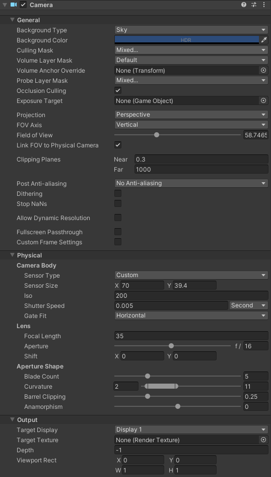
You can configure some aspects of the Camera to your liking.
E.g. you can set the field of view (fov) of the camera by changing the Field of View field or manipulating the physical camera parameters like Focal Length.
The important thing is to configure the Camera Sensor Script correctly.
Always check whether the correct Camera Object is selected and make sure that Distortion Shader and Ros Image Shader are selected.
Example Camera Sensor Script configuration
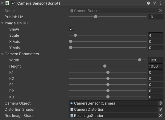
You can add the live Camera preview onto the Scene.
To do this select the Show checkbox.
Additionally you can change how the preview is displayed.
Change the Scale value to control the size of the preview (how many times smaller the preview will be compared to the actual screen size).
Move the preview on the screen by changing the X Axis and Y Axis values on the Image On Gui section.
Camera preview example
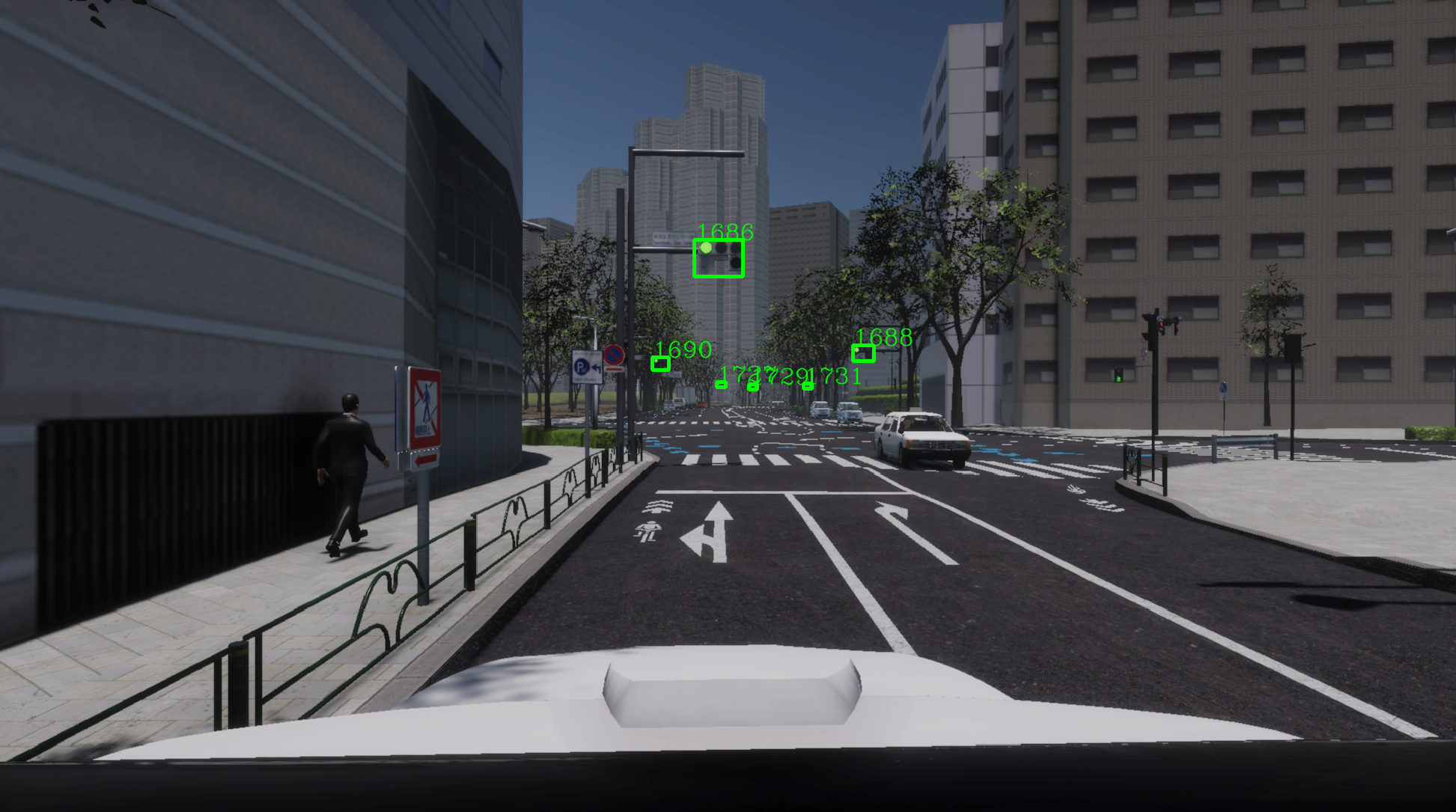
Testing camera with traffic light recognition
You can test the Camera Sensor traffic light recognition by positioning the vehicle on the Unity Scene in such a way that on the Camera preview you can see the traffic lights.
Remember to lock the Inspector view on Camera Object before dragging the whole Vehicle - this way you can see the preview while moving the vehicle.
Run the Scene the same as on this page.
Launch only the Autoware like on this page.
By default you should see the preview of traffic light recognition visualization in the bottom left corner of Autoware.
Traffic lights recognition example in Autoware
ROS message example
In this example you can see what a valid message from the Camera Sensor can look like.
$ ros2 topic echo --once /sensing/camera/traffic_light/image_raw
header:
  stamp:
    sec: 14
    nanosec: 619999673
  frame_id: traffic_light_left_camera/camera_optical_link
height: 1080
width: 1920
encoding: bgr8
is_bigendian: 0
step: 5760
data:
- 145
- 126
- 106
- 145
- 126
- 106
- 145
- 126
- 106
- 145
- 126
- 105
- 145
- 126
- 105
- 145
- 126
- 105
- 145
- 126
- 105
- 145
- 126
- 105
- 145
- 126
- 105
- 145
- 126
- 105
- 145
- 126
- 104
- 145
- 126
- 104
- 145
- 126
- 104
- 145
- 126
- 104
- 145
- 126
- 104
- 145
- 126
- 104
- 145
- 126
- 104
- 145
- 126
- 104
- 145
- 126
- 103
- 145
- 126
- 103
- 145
- 126
- 103
- 145
- 126
- 103
- 145
- 126
- 103
- 145
- 126
- 103
- 145
- 126
- 103
- 145
- 126
- 103
- 145
- 126
- 103
- 145
- 126
- 103
- 145
- 124
- 103
- 145
- 124
- 103
- 145
- 124
- 103
- 145
- 124
- 103
- 145
- 124
- 103
- 145
- 124
- 103
- 145
- 124
- 103
- 145
- 124
- 101
- 145
- 124
- 101
- 145
- 124
- 101
- 145
- 124
- 101
- 145
- 123
- 101
- 145
- 123
- 101
- 145
- 123
- 101
- 145
- 123
- '...'
---
Add a Pose Sensor
To add a Pose Sensor to your Vehicle simply locate the following directory in the Project view and drag a prefab of this Sensor into the base_link Object.
Assets/AWSIM/Prefabs/Sensors
ROS message example
In this example you can see what a valid message from the Pose Sensor can look like.
$ ros2 topic echo --once /awsim/ground_truth/vehicle/pose
header:
  stamp:
    sec: 5
    nanosec: 389999879
  frame_id: base_link
pose:
  position:
    x: 81655.7578125
    y: 50137.3515625
    z: 42.8094367980957
  orientation:
    x: -0.03631274029612541
    y: 0.0392342209815979
    z: 0.02319677732884884
    w: 0.9983005523681641
---
Test a Sensor
You can test whether the Sensor works correctly in several ways.
-
Check whether the configuration is correct.
In terminal source ROS with the following line (only if you haven't done so already).
source /opt/ros/humble/setup.bashCheck the details about the topic that your Sensor is broadcasting to with the following command.
ros2 topic info -v <topic_name>Example
In this example we can see that the message is broadcasted by AWSIM and nobody is listening. We can also examine the Quality of Service settings.
$ ros2 topic info -v /awsim/ground_truth/vehicle/pose Type: geometry_msgs/msg/PoseStamped Publisher count: 1 Node name: AWSIM Node namespace: / Topic type: geometry_msgs/msg/PoseStamped Endpoint type: PUBLISHER GID: 01.10.13.11.98.7a.b1.2a.ee.a3.5a.11.00.00.07.03.00.00.00.00.00.00.00.00 QoS profile: Reliability: RELIABLE History (Depth): KEEP_LAST (1) Durability: VOLATILE Lifespan: Infinite Deadline: Infinite Liveliness: AUTOMATIC Liveliness lease duration: Infinite Subscription count: 0 -
Check whether correct information is broadcasted.
In terminal source ROS with the following line (only if you haven't done so already).
source /opt/ros/humble/setup.bashView one transmitted message.
ros2 topic echo --once <topic_name>Example
In this example we can see the Vehicles location at the moment of executing the command.
NOTE: The position and orientation are relative to the frame in the
header/frame_idfield (base_linkin this example).$ ros2 topic echo --once /awsim/ground_truth/vehicle/pose header: stamp: sec: 46 nanosec: 959998950 frame_id: base_link pose: position: x: 81655.7265625 y: 50137.4296875 z: 42.53997802734375 orientation: x: 0.0 y: -9.313260163068549e-10 z: -6.36646204504876e-12 w: 1.0 ---