1.2. TIER IV Cameras Getting Started Guide for ADLINK ROSCube RQX-59G#
Attention
This document is based on tier4_automotive_hdr_camera version 2.1.0
Attention
This document is for the users of ADLINK RQX-59G
1.2.1. Preparation#
1.2.1.1. Required items#
ADLINK ROSCube-X RQX-59G
JetPack5.1.2 (L4T R35.4.1)installed
GMSL2 coaxial cable (FAKRA - mini FAKRA, 1:4)
TIER IV Automotive HDR Camera C1, C2 or C3
1.2.1.2. Camera connection#
Firstly, make sure that the RQX-59G is turned off.
Connect cameras to the FAKRA connectors of the cable(single FAKRA connector side). Then insert the mini FAKRA connectors of the cable to the RQX-59G’s GMSL2 ports.
Please make sure the direction of the lock clown on FAKRA connectors and mini FAKRA connectors is correct (Fig.1~3).
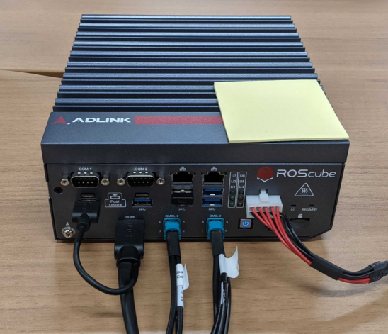
Fig. 1.6 RosCube RQX-59G#
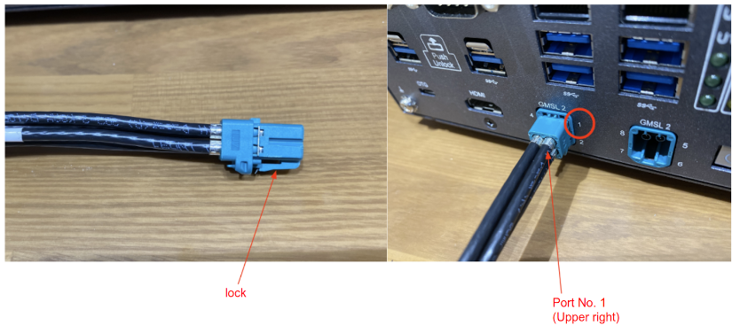
Fig. 1.7 Connector#
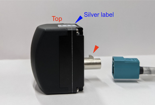
Fig. 1.8 Fakra cable insertion direction#
1.2.2. Power on and check the camera image stream output#
1.2.2.1. Power on#
Power on the RQX-59G and confirm that the power-on LED is turned on blue.
1.2.2.2. Login#
On the startup window, type the password to log in.
Default settings are shown below.
user |
|
password |
|
1.2.2.3. Camera driver installation#
New in version 1.5.0: Unified driver deb PKG can be used for RQX-59G. Before 1.5.0, please use dedicated deb PKG as described below.
Get the camera driver deb package from Github.
Copy the provided driver package file (tier4-camera-gmsl_1.4.2_59g_arm64.deb) to any directory in RQX-59G (e.g. ~/driver). Then follow the command line instructions below:
Updating the apt package. It requires an internet connection. Then, install the driver by using the
apt installcommand. Please make sure*.dtbofiles are generated at/boot.# Install sudo apt update sudo apt install make debhelper dkms sudo apt install ~/driver/tier4-camera-gmsl_*.*.*_arm64.deb # Confirm /boot/tier4-*.dtbo exists ls /boot/*.dtbo /boot/tier4-imx490-gmsl-device-tree-overlay-roscube-orin-r354.dtbo /boot/tier4-isx021-gmsl-device-tree-overlay-roscube-orin-r354.dtbo /boot/tier4-isx021-imx490-gmsl-device-tree-overlay-roscube-orin-r354.dtbo ...
To assign the camera for each port, you can use
configure-by-hardware.pyscript. Please refer to the camera driver’s README page for the details. The user needs to specify an appropriate overlay command for each user’s configuration.# For RQX-59G # Please be noted that you need to specify "1=" (not "2=") sudo /opt/nvidia/jetson-io/config-by-hardware.py -n 1="TIERIV ISX021 GMSL2 Camera Device Tree Overlay" # Confirm kernel_tegra234-p3701-0004-rqx590-nosuspend-user-custom.dtb has been generated ls /boot/*.dtb /boot/kernel_tegra234-p3701-0004-rqx590-nosuspend.dtb /boot/kernel_tegra234-p3701-0004-rqx590-nosuspend-user-custom.dtb # Then, shutdown the system sudo shutdown -h now
You can run
/opt/nvidia/jetson-io/config-by-hardware.py -lto check available overlay options.sudo /opt/nvidia/jetson-io/config-by-hardware.py -l [sudo] password for ros: Header 1 [default]: Jetson AGX CSI Connector Available hardware modules: 1. TIERIV IMX490 GMSL2 Camera Device Tree Overlay 2. TIERIV IMX728 GMSL2 Camera Device Tree Overlay 3. TIERIV ISX021 GMSL2 Camera Device Tree Overlay 4. TIERIV ISX021 IMX490 GMSL2 Camera Device Tree Overlay 5. TIERIV ISX021 IMX490 IMX728 GMSL2 Camera Device Tree Overlay
For instance, to assign all GMSL ports to the C2 camera, the overlay command should be
sudo /opt/nvidia/jetson-io/config-by-hardware.py -n 1="TIERIV IMX490 GMSL2 Camera Device Tree Overlay"
To Assign GMSL ports for both C1 and C2, the overlay command should be
sudo /opt/nvidia/jetson-io/config-by-hardware.py -n 1="TIERIV ISX021 IMX490 GMSL2 Camera Device Tree Overlay"
In this case, ports 1, 2, 5, and 6 will be assigned to C1, and ports 3, 4, 7, and 8 will be assigned to C2.
Please refer to the device driver GitHub repository for the details of the device overlay.
1.2.2.4. Check if the RQX-59G recognizes cameras#
Open a terminal window and type the following command. If it returns /dev/videoX, cameras are recognized properly as video devices.
ls /dev/video*
/dev/video0
/dev/video1
.
.
.
/dev/video7 # When 8 cameras are connected
1.2.3. Visualize camera output using GStreamer#
Open a terminal window and type the following command. Gstreamer will launch and the camera image stream will appear on a new window(Fig. 4, Fig.5).
Please also refer to GStreamer command examples for various GStreamer examples.
1.2.3.1. Case 1: 1 C1 camera is connected#
# If cameras are running in slave mode, execute this i2cset command first
i2cset -f -y 2 0x66 0x04 0xff

# Start streaming
gst-launch-1.0 v4l2src io-mode=0 device=/dev/video0 do-timestamp=true ! 'video/x-raw, width=1920, height=1280, framerate=30/1, format=UYVY' ! videoscale ! xvimagesink sync=false
1.2.3.2. Case 2: 8 C1 cameras are connected#
# If cameras are running in slave mode, execute this i2cset command first
i2cset -f -y 2 0x66 0x04 0xff

# Start streaming
gst-launch-1.0 v4l2src io-mode=0 device=/dev/video0 do-timestamp=true ! \
'video/x-raw, width=1920, height=1280, framerate=30/1, format=UYVY' ! \
xvimagesink sync=false v4l2src io-mode=0 device=/dev/video1 do-timestamp=true ! \
'video/x-raw, width=1920, height=1280, framerate=30/1, format=UYVY' ! xvimagesink sync=false \
v4l2src io-mode=0 device=/dev/video2 do-timestamp=true ! \
'video/x-raw, width=1920, height=1280, framerate=30/1, format=UYVY' ! xvimagesink sync=false \
v4l2src io-mode=0 device=/dev/video3 do-timestamp=true ! \
'video/x-raw, width=1920, height=1280, framerate=30/1, format=UYVY' ! xvimagesink sync=false \
v4l2src io-mode=0 device=/dev/video4 do-timestamp=true ! \
'video/x-raw, width=1920, height=1280, framerate=30/1, format=UYVY' ! xvimagesink sync=false \
v4l2src io-mode=0 device=/dev/video5 do-timestamp=true ! \
'video/x-raw, width=1920, height=1280, framerate=30/1, format=UYVY' ! xvimagesink sync=false \
v4l2src io-mode=0 device=/dev/video6 do-timestamp=true ! \
'video/x-raw, width=1920, height=1280, framerate=30/1, format=UYVY' ! xvimagesink sync=false \
v4l2src io-mode=0 device=/dev/video7 do-timestamp=true ! \
'video/x-raw, width=1920, height=1280, framerate=30/1, format=UYVY' ! xvimagesink sync=false \
See also
If there is a problem concerning unstable camera activation when you connect multiple cameras, please refer to this page.
1.2.3.3. Case 3: 1 C2 camera is connected#
gst-launch-1.0 v4l2src io-mode=0 device=/dev/video0 do-timestamp=true ! 'video/x-raw, width=2880, height=1860, framerate=30/1, format=UYVY' ! videoscale ! xvimagesink sync=false
1.2.3.4. Case 4: 1 C3 camera is connected#
gst-launch-1.0 v4l2src io-mode=0 device=/dev/video0 do-timestamp=true ! 'video/x-raw, width=3840, height=2160, framerate=20/1, format=UYVY' ! videoscale ! xvimagesink sync=false
When you connect multiple C2/C3 cameras
At RQX-59G, four deserializer are implemented for eight GMSL ports, and two GMSL port shares single deserializer and its bandwidth.
Even though we’ve checked that two C2 cameras can work with one deserializer, it’s best to use just one camera per deserializer, especially if you’re connecting up to four cameras.
For example:
Port 1 and 2 … Not recommended
Port 3 and 4 … Not recommended
Port 1 and port 3 … Recommended
Port 1 and 5 … Recommended
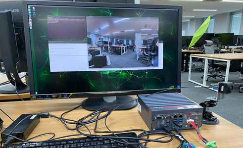
Fig. 1.9 Visualized camera output#
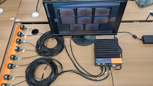
Fig. 1.10 Visualized camera output (x8 cameras)#
1.2.4. Configuration#
To change driver configuration, edit the configuration file /etc/modprobe.d/tier4-*.conf. (See following sections).
The configuration file includes the line by default. (This is the case of C1)
options tier4_isx021 trigger_mode=0 enable_auto_exposure=1 enable_distortion_correction=1
To apply the configurations, reboot RQX-59G after editing.
1.2.4.1. Switch drive mode#
Caution
To run the camera in slave mode, you need to input frame synchronization signal from RQX-59G. please check the Shutter triggering over GMSL2 to drive cameras in slave mode.
Please refer to the ADLINK’s documentation regarding trigger input how to generate the trigger signal from RQX-59G.
1.2.4.1.1. The case of C1#
Camera drive mode can be switched from Master mode to Slave mode(and vice versa) by editing the configuration file.
Master mode: Free running mode at 30fps (Default)
Slave mode: Shutter triggering mode, Shutter timing, and the frame rate can be adjusted by the FSYNC signal frequency (configurable with RQX-59G)
To switch modes, edit trigger_mode in /etc/modprobe.d/tier4-isx021.conf. (See following cases)
Drive mode |
Frame rate |
trigger_mode= |
Master |
30fps |
0 |
Slave |
Depends on the FSYNC input frequency |
1 |
1.2.4.1.2. The case of C2#
In the case of C2 the following modes can be selected by editing /etc/modprobe.d/tier4-imx490.conf respectively.
The following table shows the available settings.
Drive mode |
Frame rate |
trigger_mode= |
Master |
10fps |
0 |
Slave |
10fps |
1 |
Master |
20fps |
2 |
Slave |
20fps |
3 |
Master |
30fps |
4 |
Slave |
30fps |
5 |
1.2.4.2. Enable/Disable Lens Distortion Correction (LDC)#
Note
This setting is common for C1, C2 and C3.
To enable LDC, set the flag enable_distortion_correction=1 (default).
To disable LDC, set the flag enable_distortion_correction=0.
1.2.4.3. Enable/Disable auto exposure (AE)#
Note
This setting is common for both C1, C2 and C3.
To enable AE, set the flag enable_auto_exposure=1 (default).
To disable AE, set the flag enable_auto_exposure=0.
1.2.4.4. Setting exposure time#
1.2.4.4.1. The case of C1#
In the case of C1, users can specify three types of exposure time via variables named shutter_time_min, shutter_time_mid, and shutter_time_max.
The actual exposure time of C1 transits these three (and linearly interpolated values) corresponding to the illuminance.
The values for the variables should be specified in microseconds. Users who would like to fix exposure time under arbitral illuminance conditions can set the exact same value for these variables.
For example, the following configuration in /etc/modprobe.d/tier4-isx021.conf fixes exposure time to 11 ms:
shutter_time_min=11000 shutter_time_mid=11000 shutter_time_max=11000
1.2.4.4.2. The case of C2#
Likewise C1, C2 also has capability to set two types of exposure time via variables named shutter_time_min and shutter_time_max.
The unit of the value for these variables is also microseconds.
For example, the following configuration in /etc/modprobe.d/tier4-imx490.conf fixes exposure time to 11 ms:
shutter_time_min=11000 shutter_time_max=11000
1.2.5. Shutter triggering over GMSL2#
Camera operation in slave mode requires triggering signals input (FSYNC input) over GMSL2. Please refer to ADLINK’s documentation for how to configure the FSYNC parameters and GPIO settings.
1.2.5.1. Preparation to drive cameras in slave mode#
Check the HW version of your RQX-59G by executing i2cget -f -y 2 0x66 0x01 on a terminal and follow the instructions below.
Please confirm that returned value is at least 0x24.
i2cget -f -y 2 0x66 0x01
0x24
1.2.5.2. Input FSYNC frequency for C1#
You can input any frequency that is slower than 30fps.
1.2.5.3. Input FSYNC frequency for C2#
For C2, the allowed FSYNC frequency depends on the drive modes. Please refer to the below list.
In the case of 30fps mode (
trigger_mode=5): 15 < f <= 30 fpsIn the case of 20fps mode (
trigger_mode=3): 10 < f <= 20 fpsIn the case of 10fps mode (
trigger_mode=1): 5 < f <= 10 fps
1.2.5.4. FPS check#
To check the FPS setting with a visualized video, please execute the following commands.
The camera is connected to only port 1
gst-launch-1.0 v4l2src io-mode=0 device=/dev/video0 do-timestamp=true ! 'video/x-raw, width=1920, height=1280, framerate=30/1, format=UYVY' ! fpsdisplaysink video-sink=xvimagesink sync=false
Cameras are connected to ports 1 and 2
gst-launch-1.0 v4l2src io-mode=0 device=/dev/video0 do-timestamp=true ! 'video/x-raw, width=1920, height=1280, framerate=30/1, format=UYVY' ! xvimagesink sync=false v4l2src io-mode=0 device=/dev/video1 do-timestamp=true ! 'video/x-raw, width=1920, height=1280, framerate=30/1, format=UYVY' ! fpsdisplaysink video-sink=xvimagesink sync=false