System Architecture#
The scenario_simulator_v2 consists of the three components: test runner, openscenario_interpreter, and simulator.
Each component has the following features:
-
test_runner
The test_runner launches Autoware and other components in this tool.
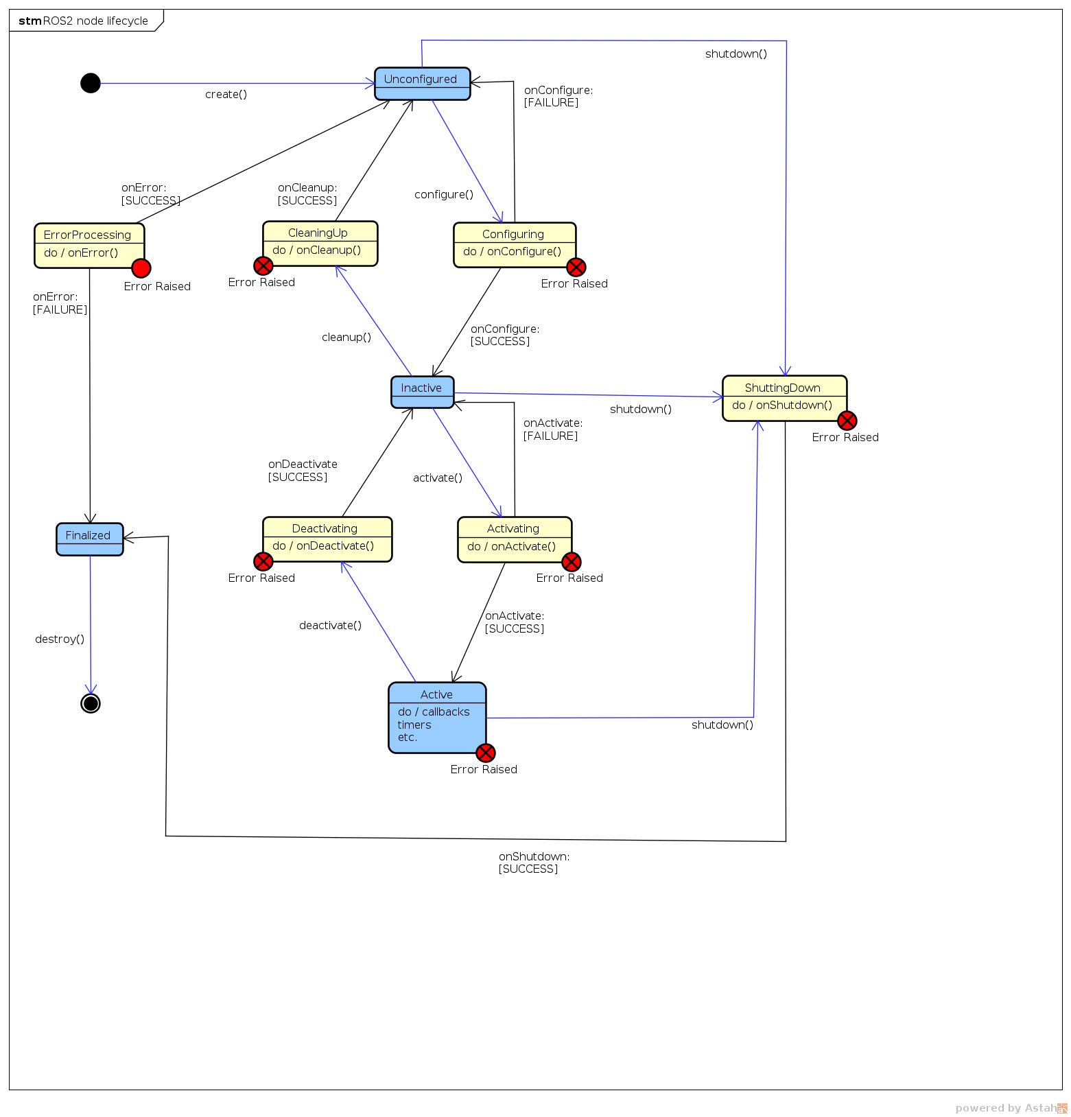
The test_runner communicates with "openscenario_interpreter" with the ROS 2 lifecycle. (https://design.ros2.org/articles/node_lifecycle.html) -
openscenario_interpreter
The test runner communicates with the openscenario_interpreter with the rclcpp lifecycle.
The openscenario_interpreter is a rclcpp lifecycle component.
 When the openscenario_interpreter launched, the state of the openscenario_interpreter is "Unconfigured".
When the test runner launched, the test runner configures the openscenario_interpreter and the state of the openscenario_interpreter becomes "Inactive".
After that, the test runner activates the openscenario_interpreter and moves the state into "Active". When the exception is thrown in the openscenario interpreter, the openscenario interpreter moves into "Inactive" state. -
simulator
The simulator component communicates with the openscenario_interpreter by using ZeroMQ. You can use any simulators by adapting the ZeroMQ API. The simple sensor simulator is a reference implementation of the simulator component.