1.7. Camera Operation and Configuration Guide#
Attention
This document explains the common operations and configurations for the TIER IV Automotive HDR Cameras (C1/C1-MP, C2/C2-MP, and C3) after the successful installation of the camera driver.
This page explains the camera control functions provided as standard in the TIER IV Automotive HDR Camera driver, as well as the methods for image acquisition and display.
1.7.1. Confirm the Camera Devices Connection#
Before acquiring images, verify if the cameras are recognized as v4l2 devices. Open a terminal and run the following command. If the number of video devices matches the number of connected cameras, the camera recognition check is complete.
ls /dev/video*
/dev/video0
/dev/video1
.
.
Note
After installing the drivers and rebooting, you may encounter error messages related to I2C write errors (e.g., Max9295 I2C write failed) in the kernel logs (dmesg or syslog). These errors are typically caused by ports where cameras are not connected and can be safely ignored as long as the connected cameras are recognized as /dev/video*.
1.7.2. Module Parameter Configuration#
To modify camera driver settings, edit the /etc/modprobe.d/tier4-*.conf file (e.g., tier4-isx021.conf for C1/C1-MP, tier4-imx490.conf for C2/C2-MP, tier4-imx728.conf for C3).
The configuration file contains lines similar to the following:
# /etc/modprobe.d/tier4-isx021.conf
options tier4_isx021 trigger_mode=0 enable_auto_exposure=1 enable_distortion_correction=1
After editing these flags, you must restart the system for the changes to take effect.
1.7.2.1. Enabling/Disabling Lens Distortion Correction (LDC)#
Note
This setting is common for the TIER IV Automotive HDR Cameras.
You can enable or disable the Lens Distortion Correction (LDC) feature by modifying the enable_distortion_correction flag.
To enable LDC:
enable_distortion_correction=1(default)To disable LDC:
enable_distortion_correction=0
1.7.2.2. Enabling/Disabling Auto Exposure (AE)#
Note
This setting applies only to C1/C1-MP. Other cameras are fixed in AE mode. To fix the shutter time, set shutter_time_min and shutter_time_max to the same value.
To enable AE:
enable_auto_exposure=1(default)To disable AE:
enable_auto_exposure=0
1.7.2.3. Setting Exposure Time#
1.7.2.3.1. The case of C1/C1-MP#
Users can specify three types of exposure time via variables named shutter_time_min, shutter_time_mid, and shutter_time_max. The actual exposure time transits these three (and linearly interpolated values) corresponding to the illuminance.
Values are specified in microseconds. To fix the exposure time under arbitral illuminance conditions, set the exact same value for all three variables.
Example (fixes exposure time to 11 ms):
shutter_time_min=11000 shutter_time_mid=11000 shutter_time_max=11000
1.7.2.3.2. The case of C2/C2-MP, C3#
C2/C2-MP and C3 have the capability to set two types of exposure time via shutter_time_min and shutter_time_max (in microseconds).
Example (fixes exposure time to 11 ms):
shutter_time_min=11000 shutter_time_max=11000
For other parameter adjustments, please refer to the t4cam_ctrl user manual.
1.7.3. Drive Mode Configuration (Free-run / Trigger Modes)#
Camera drive modes can be configured by editing the trigger_mode variable in the configuration file. All camera models (C1/C1-MP, C2/C2-MP, C3) share a unified set of drive modes.
If your ECU supports FSYNC (e.g., ADLINK RQX-58G / RQX-59G, Connect Tech Anvil), camera operation in Trigger modes requires triggering signals input over GMSL2.
Warning
Drive mode switching (Trigger modes) requires FSYNC input. This is NOT supported on Jetson AGX Orin/Xavier Developer Kits or Vecow EAC-5000, as they lack an FSYNC input function. Changing from the default settings on these ECUs may cause unintended behavior.
1.7.3.1. Drive Mode Definitions#
Free-run mode: The camera operates autonomously and triggers the shutter internally.
Trigger mode: The camera operates synchronized with the trigger signal (FSYNC) from the ECU. There are two types of trigger modes depending on the synchronization target:
Readout sync: The camera starts image output to the ECU synchronized with the trigger signal.
Shutter sync: The camera starts the shutter synchronized with the trigger signal.
1.7.3.2. Configuration Table#
You can select the desired mode by setting the trigger_mode value.
trigger_mode |
Drive Mode |
Target FPS |
Allowed FSYNC frequency |
Supported Cameras |
0 |
Free-run mode |
10fps |
N/A |
All |
1 |
Trigger mode (Readout sync) |
10fps |
5 < f <= 10 fps |
C1/C1-MP, C2/C2-MP |
2 |
Free-run mode |
20fps |
N/A |
All |
3 |
Trigger mode (Readout sync) |
20fps |
10 < f <= 20 fps |
C1/C1-MP, C2/C2-MP |
4 |
Free-run mode |
30fps |
N/A |
All |
5 |
Trigger mode (Readout sync) |
30fps |
15 < f <= 30 fps |
C1/C1-MP, C2/C2-MP |
6 |
Trigger mode (Shutter sync) |
Depends on FSYNC |
f <= 30 fps |
C1/C1-MP, C3 |
1.7.3.3. Synchronization Details (Shutter Sync vs. Readout Sync)#
Automotive applications require precise capture synchronization across multiple cameras and other sensor modalities (like LiDAR or RADAR). The TIER IV Automotive HDR Cameras support two trigger-based synchronization mechanisms depending on the camera’s image sensor architecture:
1.7.3.3.1. 1. Shutter Sync#
Supported Cameras: C1/C1-MP, C3
Mechanism: The camera starts exposure immediately upon receiving the external trigger signal (FSYNC) from the ECU over GMSL2. Without FSYNC input, the camera does not output any image frames.
Timing Diagram:
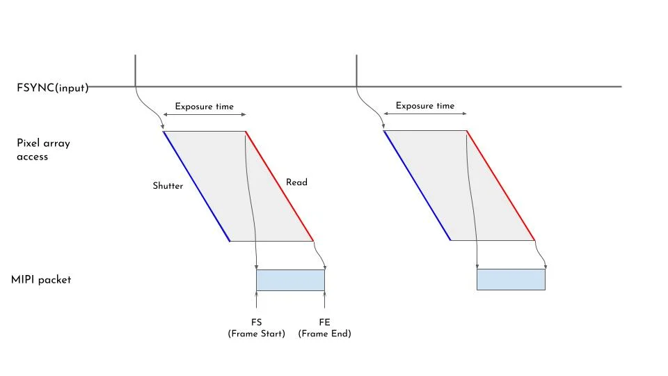
Fig. 1.9 Shutter Sync timing diagram#
1.7.3.3.2. 2. Readout Sync#
Supported Cameras: C1/C1-MP, C2/C2-MP
Mechanism: The FSYNC signal adjusts or triggers the readout timing rather than exposure. The camera adjusts its readout start timing by measuring the time difference between its internal synchronization timing and the FSYNC reception timing. This adjustment takes effect 2 frames after the FSYNC is received. Exposure starts automatically prior to the readout based on the camera or user exposure configuration. If no FSYNC is input, the camera falls back to outputting image data autonomously based on its original frame rate setting.
Timing Diagrams:
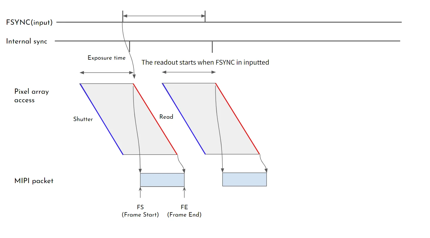
Fig. 1.10 Readout Sync timing adjustment#
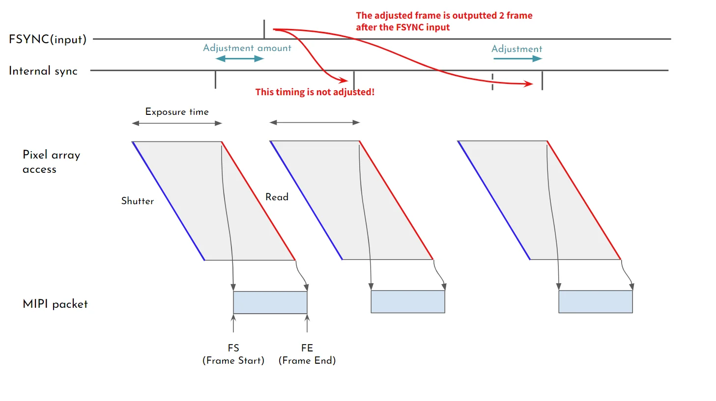
Fig. 1.11 Readout Sync adjustment frame#
1.7.3.4. ECU-Specific Trigger Parameters#
If you use Trigger modes (Readout sync or Shutter sync), certain ECUs require an additional fsync_mfp parameter in the configuration file to enable the FSYNC function.
Connect Tech Anvil: Set
fsync_mfp=7Syslogic RML-A4AGX: Set
fsync_mfp=6
Example for Anvil:
options tier4_isx021 trigger_mode=1 enable_auto_exposure=1 fsync_mfp=7
1.7.3.5. Preparation for Trigger Modes (ADLINK RQX-58G / RQX-59G specific)#
If you are running the cameras in Trigger mode on a supported ECU like ADLINK RQX-58G / RQX-59G, specific preparation may be required before starting the stream.
Check the HW version of your RQX-58G / RQX-59G by executing the following command on a terminal:
i2cget -f -y 2 0x66 0x01
Execute the following command before starting streaming. The system requires this preparation only once after its boot.
i2cset -f -y 2 0x66 0x04 0xff
No preparation is required.
1.7.4. Camera Image Acquisition (v4l2-ctl)#
Caution
In Trigger modes, image acquisition cannot be confirmed unless the trigger signal is successfully output to the camera.
You can verify if images are being acquired correctly by entering the following command in a terminal:
v4l2-ctl --stream-mmap -d /dev/video0
If the output looks similar to the following, the images are being successfully acquired from the camera.
$ v4l2-ctl --stream-mmap -d /dev/video0
<<<<<<<<<<<< 10.00 fps
<<<<<<<<<<<< 10.00 fps
<<<<<<<<<<<< 10.00 fps
    :
    :
1.7.5. Camera Image Acquisition (GStreamer)#
Open a terminal and execute the following commands to start image acquisition using GStreamer. A new window will open, displaying the camera image.
Caution
Bandwidth Restrictions for C2/C2-MP and C3 Cameras: Depending on your ECU (e.g., ADLINK RQX-58G/59G), connecting two C2/C2-MP or C3 cameras to a single deserializer board (e.g., Port 1 & 2 together) may exceed bandwidth limits and cause streaming to fail. Please refer to your specific ECU’s installation guide for port assignment recommendations.
Note
You can also utilize the gstreamer launch script.
If you encounter the error message
no element "v4l2src", please delete the directory~/.cache/gstreamer-1.0and try the command again.
1.7.5.1. Example 1: Evaluation with a C1/C1-MP camera#
gst-launch-1.0 v4l2src io-mode=0 device=/dev/video0 do-timestamp=true ! 'video/x-raw, width=1920, height=1280, framerate=30/1, format=UYVY' ! videoscale ! xvimagesink sync=false
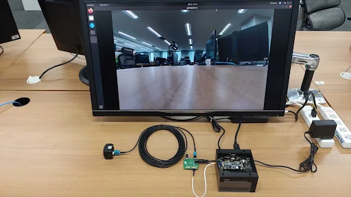
Fig. 1.12 Example of Camera Image Data Acquisition#
1.7.5.2. Example 2: Evaluation with Multiple C1/C1-MP cameras#
For 4 cameras:
gst-launch-1.0 v4l2src io-mode=0 device=/dev/video0 do-timestamp=true ! \
'video/x-raw, width=1920, height=1280, framerate=30/1, format=UYVY' ! \
xvimagesink sync=false v4l2src io-mode=0 device=/dev/video1 do-timestamp=true ! \
'video/x-raw, width=1920, height=1280, framerate=30/1, format=UYVY' ! xvimagesink sync=false \
v4l2src io-mode=0 device=/dev/video2 do-timestamp=true ! \
'video/x-raw, width=1920, height=1280, framerate=30/1, format=UYVY' ! xvimagesink sync=false \
v4l2src io-mode=0 device=/dev/video3 do-timestamp=true ! \
'video/x-raw, width=1920, height=1280, framerate=30/1, format=UYVY' ! xvimagesink sync=false
For 8 cameras: Add v4l2src device=/dev/video4 through video7 following the same pattern.
1.7.5.3. Example 3: Evaluation with a C2/C2-MP camera#
gst-launch-1.0 v4l2src io-mode=0 device=/dev/video0 do-timestamp=true ! 'video/x-raw, width=2880, height=1860, framerate=30/1, format=UYVY' ! videoscale ! xvimagesink sync=false
1.7.5.4. Example 4: Evaluation with a C3 camera#
gst-launch-1.0 v4l2src io-mode=0 device=/dev/video0 do-timestamp=true ! 'video/x-raw, width=3840, height=2160, framerate=20/1, format=UYVY' ! videoscale ! xvimagesink sync=false
** Example 5: Checking FPS (fpsdisplaysink)**
To verify the FPS setting with a visualized video, use the fpsdisplaysink element:
gst-launch-1.0 v4l2src io-mode=0 device=/dev/video0 do-timestamp=true ! 'video/x-raw, width=1920, height=1280, framerate=30/1, format=UYVY' ! fpsdisplaysink video-sink=xvimagesink sync=false
1.7.6. Recording Image Data#
You can use GStreamer to record the image data while encoding it in H.265. Please modify the bitrate, file name, and other parameters according to your needs.
Example 1: Recording with a single C1/C1-MP camera
gst-launch-1.0 -e v4l2src io-mode=0 device=/dev/video0 do-timestamp=true ! 'video/x-raw, width=1920, height=1280, framerate=30/1, format=UYVY' ! nvvidconv ! nvv4l2h265enc bitrate=3000000 ! h265parse ! qtmux ! filesink location=out.mp4
Example 2: Recording with two C1/C1-MP cameras
gst-launch-1.0 -e v4l2src io-mode=0 device=/dev/video0 do-timestamp=true ! 'video/x-raw, width=1920, height=1280, framerate=30/1, format=UYVY' ! tee name=camera1 v4l2src io-mode=0 device=/dev/video1 do-timestamp=true ! 'video/x-raw, width=1920, height=1280, framerate=30/1, format=UYVY' ! tee name=camera2 camera1. ! nvvidconv ! nvv4l2h265enc bitrate=3000000 ! h265parse ! qtmux ! filesink location=out_1.mp4 camera2. ! nvvidconv ! nvv4l2h265enc bitrate=3000000 ! h265parse ! qtmux ! filesink location=out_2.mp4
In the case of the C2/C2-MP and C3 cameras, please change the width, height, and framerate settings appropriately:
width=2880andheight=1860for the C2/C2-MPwidth=3840,height=2160andframerate=20for the C3