1. C1 Camera Technical Reference Manual#
1.1. Overview#
The C1 camera is a GMSL (Gigabit Multimedia Serial Link) camera specifically designed for automotive applications. It has a resolution of 2.5 MP at 1920 x 1280 px.
Featuring Sony Semiconductor Solutions’ ISX021 back-side illumination stacked CMOS image sensor SoC, this camera enables HDR imaging over 120dB, LED flicker mitigation (LFM), and motion artifact-free image capturing at a frame rate of up to 30fps.
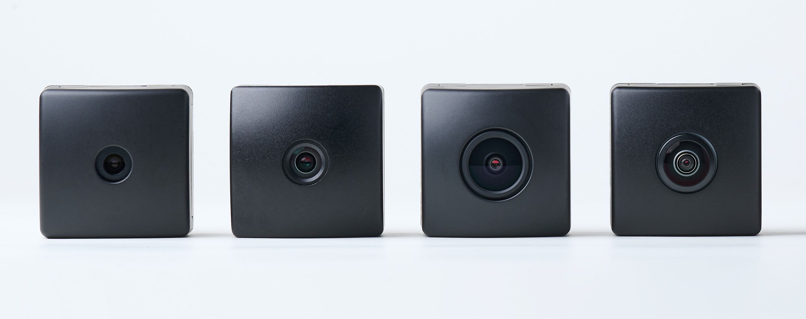
With a variety of lens options available, the C1 camera can be adapted to many applications. The lens undergoes a 6-axis active adjustment during installation, allowing it to achieve optimal sharpness even in harsh temperature environments.
The ISP (Image Signal Processor) built into the C1 camera’s image sensor performs various image processing tasks, including lens distortion correction, to achieve optimal image quality for automotive applications. The C1 camera also supports an external triggering mechanism, which is essential to achieve capture synchronization with other sensor modalities such as LiDAR or RADAR, enabling sensor fusion.
Designed for automotive mass production, the C1 camera is ready to use. All key components comply with AEC-Q100 (Grade 2), Q101, and Q200 standards, and are designed to pass automotive-grade reliability tests.
1.2. Mechanical specifications#
1.2.1. Camera size and weight#
Model Name |
C1-046 |
C1-085 |
C1-120 |
C1-198 |
|---|---|---|---|---|
Camera size |
38.5mm x 38.5mm x 42.19mm |
38.5mm x 38.5mm x 43.21mm |
38.5mm x 38.5mm x 48.93mm |
38.5mm x 38.5mm x 40.44mm |
Camera weight |
48g |
53g |
55g |
51g |
1.2.2. Connector#
Fakra Z code with metal shielding
1.2.3. Outline diagram#
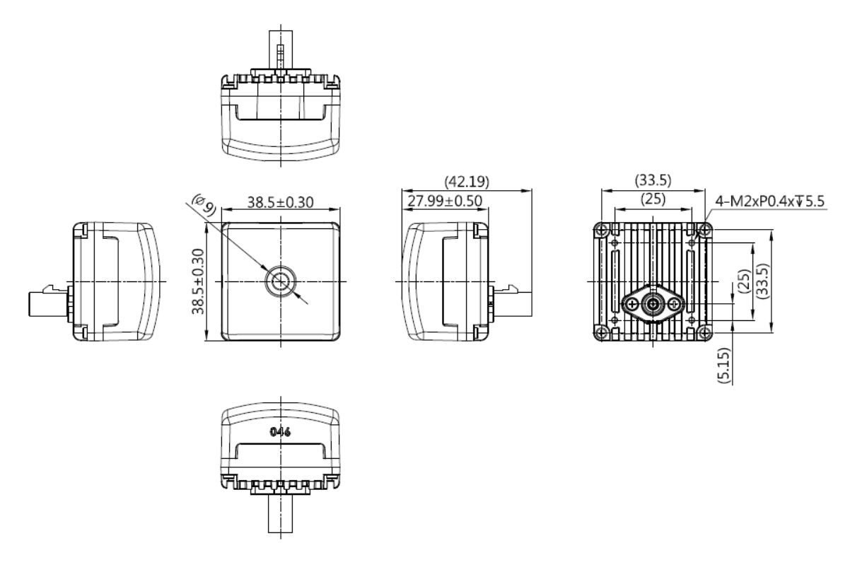
Fig. 1.20 C1-046 (46°)#
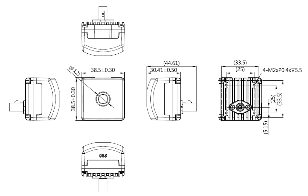
Fig. 1.21 C1-085 (85°)#
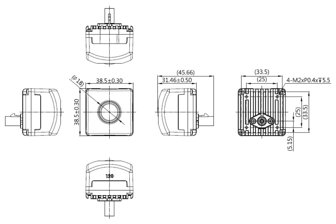
Fig. 1.22 C1-120 (120°)#
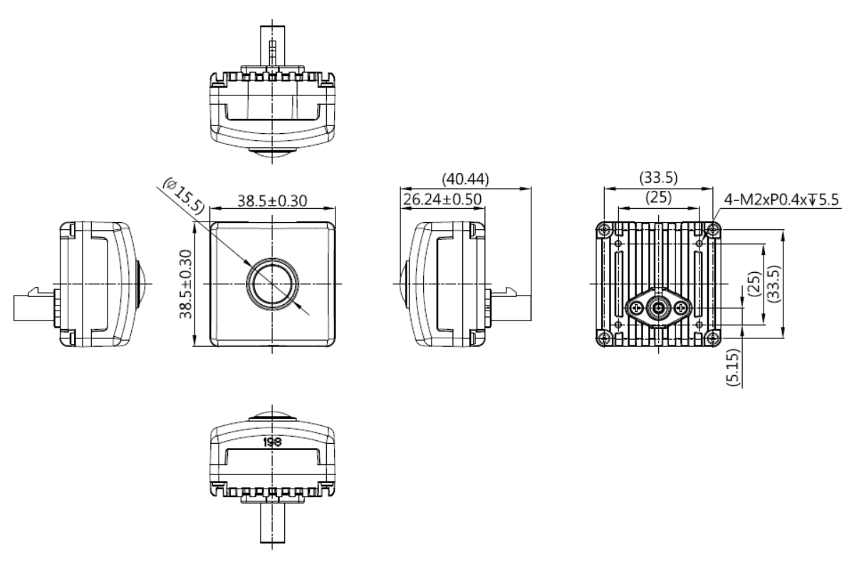
Fig. 1.23 C1-198 (198°)#
1.2.4. 3-dimensional CAD data#
3-dimensional CAD data can be downloaded. Refer to the download link
1.3. Lens specifications#
Model Name |
C1-046 |
C1-085 |
C1-120 |
C1-198 |
|---|---|---|---|---|
Field of View (FoV)Horizontal/Vertical(LDC: Lens Distortion Correction) |
LDC OFF46deg/32degLDC ON46deg/32deg |
LDC OFF85deg/56degLDC ON78deg/56deg |
LDC OFF120deg/77degLDC ON111deg/77deg |
LDC OFF198.6deg/128.2degLDC ON162deg/125deg |
F# |
2.2 |
1.7 |
1.8 |
2 |
EFL |
6.72mm |
3.955mm |
2.9mm |
1.723mm |
TTL |
14.9mm |
18.59mm |
21.01mm |
15.79mm |
Image Circle |
\(\phi\) 7.942mm |
\( \phi \) 7.84mm |
> \( \phi \) 7.2mm |
\( \phi \) 5.9mm Max |
IRCF |
650±10nm |
648±10nm |
650±15nm |
650±10nm |
Resolution (TV Line) |
750TVL @ Center, 500TVL @ 70% Image height |
750TVL @ Center, 500TVL @ 70% Image height |
750TVL @ Center, 500TVL @ 70% Image height |
750TVL @ Center, 500TVL @ 70% Image height |
Depth of Field |
185cm - Infinity Focus peaking distance: 400cm |
112cm - Infinity Focus peaking distance: 400cm |
106.7cm - Infinity Focus peaking distance: 400cm |
33cm - Infinity Focus peaking distance: 100cm |
Attention
It is not possible to obtain the internal parameters and distortion correction coefficients from the camera. For details, For more details, please see below.
1.3.1. Lens Mount#
Glued, active alignment applied.
Attention
The lens cannot be exchanged.
1.4. Electrical specifications#
1.4.1. Power supply method#
Power over coax cable
1.4.2. Power consumption#
1.7W (under room temperature)
1.4.3. Power supply level#
9 - 12 [V]
1.5. Key components#
1.5.1. Image Sensor#
Sony Semiconductor Solutions ISX021
1.5.2. Optical format#
Diagonal 6.99mm, type 1/2.57
1.5.3. Pixel size#
3.0um
1.5.4. High dynamic range#
Available, 120dB equivalent
1.5.5. LED flicker mitigation#
Available.
1.5.6. Serializer#
Analog Devices MAX9295A
1.5.7. ISP#
Integrated on the image sensor
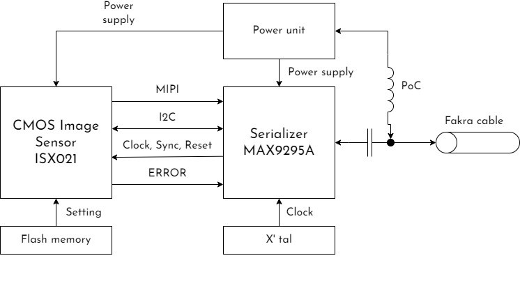
1.6. Block diagram#
1.7. Camera function#
1.7.1. Output interface#
1.7.2. Output image format#
YUV422 8bit. 16bit/pixel bit depth.
1.7.3. Output image size#
1920 x 1280
1.7.4. Framerate#
Up to 30fps
1.7.5. Shutter type#
Rolling Shutter
Note
Shutter type cannot changed
1.7.6. Drive mode#
Master mode: The camera operates based on its framerate setting.
Shutter trigger mode: See below for the details.
1.7.7. Synchronization#
C1 camera supports trigger-based synchronization. The host (e.g., ECU) sends a synchronization signal (FSYNC) via the GMSL interface to the image sensor. When the image sensor receives an FSYNC signal, the exposure starts. After the exposure time which is controlled by the camera or user, the readout will start. Then, the MIPI packet is transmitted by the camera.
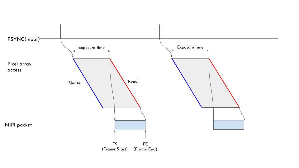
In this mode, an FSYNC input is required to output an image frame. Without FSYNC input, the camera will not output the image data.
The FSYNC pin of the image sensor is connected to the MFP3 GPIO of the serializer. The user needs to configure the deserializer so the synchronization output pin on the ECU is mapped to this pin.
1.7.8. Embedded data output#
Supported.
New in version camera: driver v1.4.1
Supports embedded data for C1
1.8. ISP function#
ISP setting can be controlled by using T4cam-ctrl software.
AE (Auto Exposure)
AWB (Auto White Balance)
Basic image-tuning interfaces
Hue
Saturation
Contrast
Brightness
Sharpness
1.9. Quality/Environmental specifications#
1.9.1. Operating temperature range#
-40° ~ 85°
1.9.2. Storage temperature range#
-40°C ~ 105°C
1.9.3. Product reliability#
Please contact our authorized agency for the details.
1.9.4. Compliances#
CE
RoHS
FCC
Can ICES-3
UKCA
RCM
KC
1.9.5. Safety#
LVD compliant
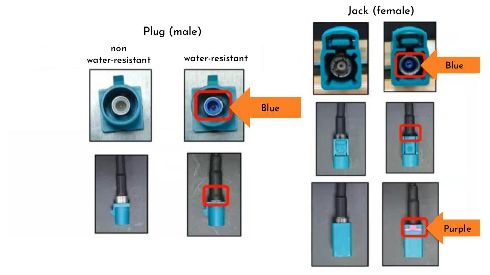
1.9.6. Ingress protection#
The camera has IP69K-grade ingress protection.
Note
To realize IP69K, the user needs to use a water-resistant Fakra cable. To distinguish the water-resistant and non-water-resistant cable, please refer below.