GMSL2-USB 3.0 Conversion Kit User Manual#
This manual is for users of the TIER IV's GMSL2-USB3.0 Converson Kit. If you have any questions or issues that are not resolved by this manual, please contact the dealer you purchased from.
Release Note#
| Date | Description |
|---|---|
| Feb. 7, 2023. | Publication of the first edition |
Introduction#
The GMSL2-USB3.0 Conversion Kit allows TIER IV Automotive HDR Camera C1/C2 (hereinafter referred to as C1, C2 camera) cameras to be connected to a USB Type-C (3.0) port and captures video through UVC(USB Video Class). You can use C1, C2 camera in applications on a computer that does not have the GMSL interface.
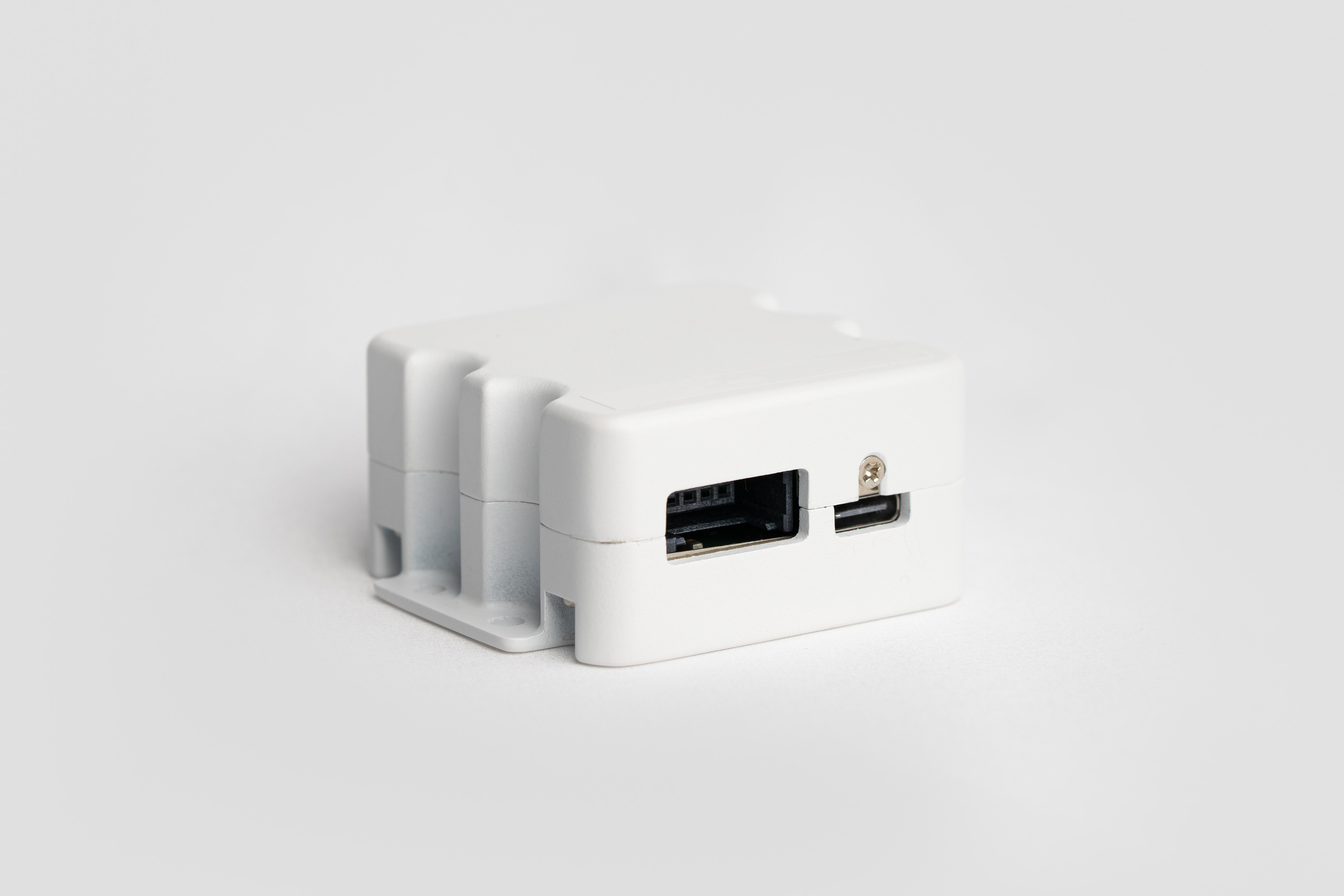
Interface description#
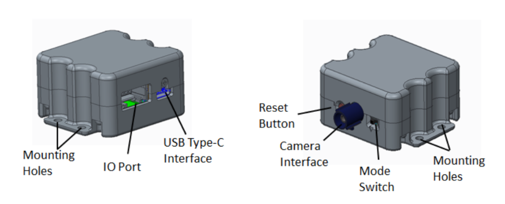
Camera Interface#
The connection interface between the camera and the kit is a 50-ohm coaxial cable with a Fakra plug (C code Blue) installed.
USB Type-C Interface#
The connection interface between the kit and the host is a USB Type-C supports up to USB3.0 Super Speed. Also you can use industry-standard screw locking or non-screw-locking USB Type-C cables.
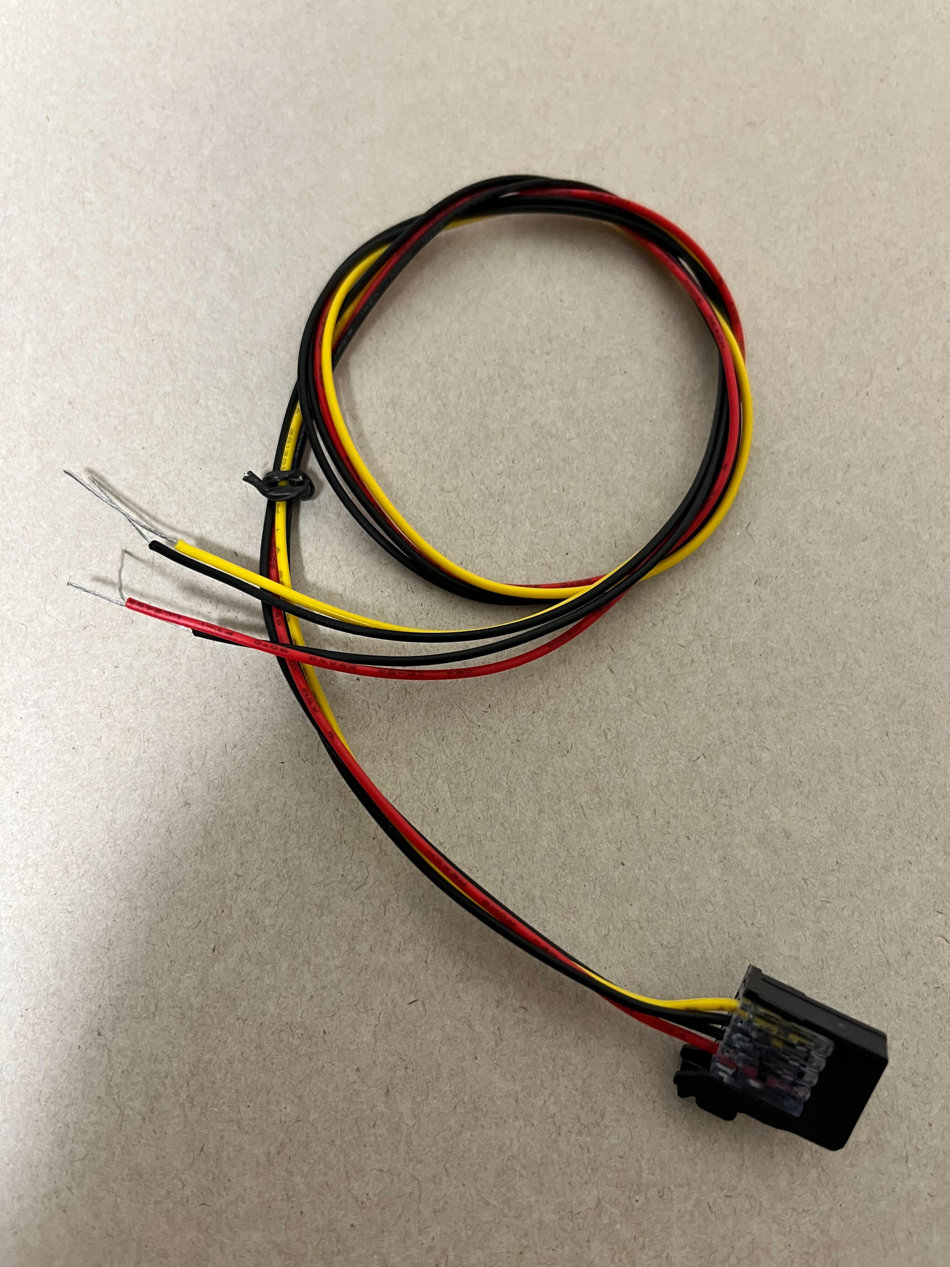
IO Port (embedded RITS 4P connector)#
This is for FSYNC signal(frame sync.) and External DC-IN power supply. This port uses the 4-P RITS Board Mount Headers(TE Connectivity 156994-4). The part number of the corresponding Plug connector is x-1473562-4. If you need to use this port, please prepare the cable yourself using the above plug.
Each pin is as follows:
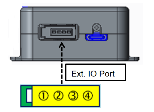
| Port | Name | Description |
|---|---|---|
| 1 | External power supply | Supply voltage range: 9V ~ 12V( for C1/C2 Camera), Supply current required: > 1A. Note: This is an alternative option to supply power to camera externally when USB host can not provide enough power. |
| 2 | GND | |
| 3 | GND | |
| 4 | External FSYNC signal input (only for camera Trigger mode) | FSYNC can support with external output driving type for Push-pull or Open-Drain. If FSYNC pair with external output driving of Push-Pull type: The input signal voltate: High level: 1.8V ~ 24V, and Low Level: < 0.2V. If FSYNC pair with external output driving of Open-Drain type: Because the FSYNC internal has build-in a Pull-Up register, so external open-drain dricing do not need pull-up. The require of external device driving: The driving Low sink current : > 1mA, and Low Level: < 0.2V. FSYNC Frequency: Depend on camera module frame rate support, such as <=30Hz for C1 camera, Fixed 10Hz C2 Camera. FSYNC signal high level pulse width(T-pulse): 1ms < T-pulse < 30ms |
Reset Button#
Push-and-release button for conversion kit reset.
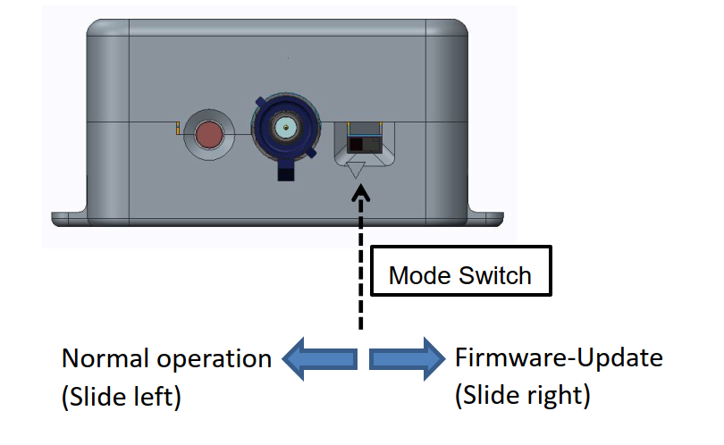
Operation Mode Switch#
A slide switch for selecting the operation mode is provided. Slide it to the left for normal operation and to the right for firmware updates.
How to use#
Upon purshasing the kit, it will be set to C1 Free-run mode(freerun, 30fps). If you need to use it in this mode, please follow the instructions for Free-run mode. If you require a diffrent mode, please refer to the Firmware List and Change the Camera Mode.
Firmware List#
| Camera mode | Description | Image file |
|---|---|---|
| C1 Free-run mode (default mode) | For C1 camera, Free-run, 10,20,30FPS | C1_Free-run_v1.10a.img |
| C1 Hardware Trigger mode | For C1 camera, fsync trigger from IO port | C1_Trigger_v1.00b.img |
| C2 Free-run mode | For C2 Camera, Freerun, 10FPS | C2_Free-run_v1.00c.img |
| C2 Hardware Trigger mode | For C2 Camera, fsync trigger from IO port | C2_Trigger_v1.00d.img |
Free-run mode#
Connect as shown in the following figure and instrunctions:
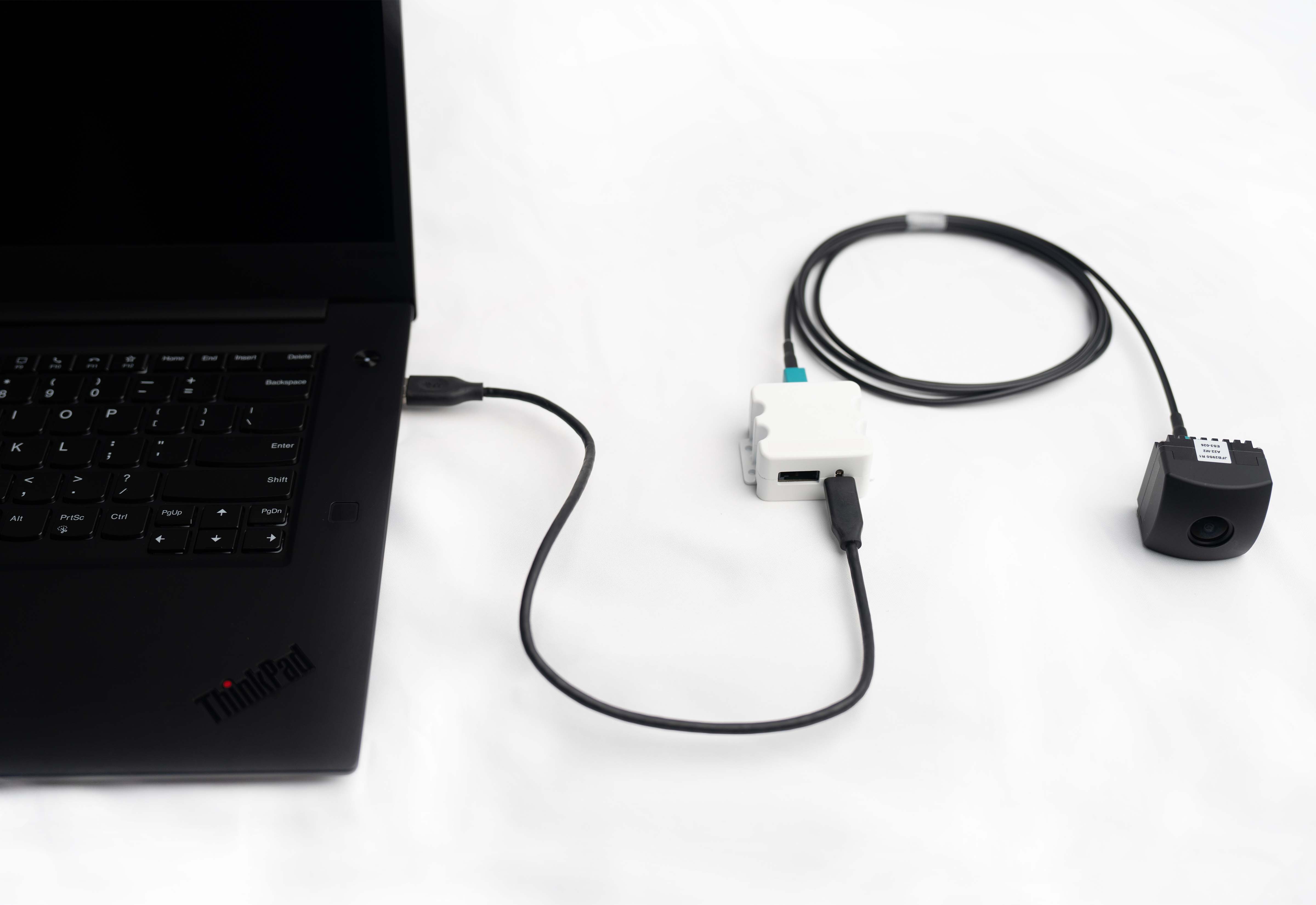
Please connect the camera to the conversion kit the Fakra cable, and then connect the host using a USB cable. If the order is reversed (connecting the host first with the USB cable before connecting the camera), you need to press the reset button. This Kit will be recognized as a UVC camera device when connected via USB. No driver installation is required to use the device as a UVC camera. After connecting, select "GMSL2-USB3.0 Conversion Kit" from the camera using application and start using it.
If the camera device cannot be found, or if the image is not normal, please check the Trouble Shooting section for more information.
Trigger mode#
Connect the RITS connector with a cable and transmit signals in the same way as in Free-run mode. Please refer to the section on IO Port embedded RITS 4P connector for the connector shape and the signals to be transmitted. Also, be aware that you must change the mode beforehand by updating the firmware.
For C1 cameras, the shutter will open when the signal is transmitted and close after the exposure time. For C2 cameras, please consult with support.
Regarding the use of the camera, other than the sending of the shutter timing, it is the same as the Free-run mode.
Usage examples in applications#
gstreamer#
This section describes video acquisition with gstreamer. The steps described in this item are for Ubuntu20.04.
First, install gstreamer and v4l-utils with the following command. If they are already installed, this item is not necessary to execute.
$ sudo apt install libgstreamer1.0-0 gstreamer1.0-tools
$ sudo apt install v4l-utils
Next, check the device name in the environment to be used. The following command displays the connected devices. If the device name is already known, this item is not necessary to execute.
v4l2-ctl --list-devices
Below is an example of the output.
Integrated IR Camera: Integrate (usb-0000:00:14.0-12):
    /dev/video2
    /dev/video3

GMSL2-USB3.0 Conversion Kit (usb-0000:00:14.0-2):
    /dev/video4
    /dev/video5

Integrated Camera: Integrated C (usb-0000:00:14.0-8):
    /dev/video0
    /dev/video1
As the results vary depending on the environment used, please look for the item displayed as "GMSL2-USB3.0 Conversion Kit" and the device, "/dev/video4", on top of it. Then, run gstreamer with the following command.
gst-launch-1.0 v4l2src io-mode=0 device=/dev/video4 do-timestamp=true ! 'video/x-raw, width=1920, height=1280, framerate=30/1, format=UYVY' ! videoscale ! xvimagesink sync=false
Additionally, the framerate can be set in 3 patterns at 10/20/30 fps during this time. To set the framerate to 10 fps, execute it as follows.
gst-launch-1.0 v4l2src io-mode=0 device=/dev/video4 do-timestamp=true ! 'video/x-raw, width=1920, height=1280, framerate=10/1, format=UYVY' ! videoscale ! xvimagesink sync=false
ROS2#
We will explain the usage of two types of nodes, the "usb_cam" node and the "v4l2 camera" node that target the ROS2 Galactic distribution. But if the node supports the UVC format with UYVY color, video can be acquired. Please install ROS2 Galactic in advance by referring to the official website or others.
usb_cam node#
Please clone and build the usb_cam node from the following repository, and refer to the README of the repository for the build instructions.
usb_cam node repository: https://github.com/tier4/usb_cam
Please execute with the following command after the build is completed.
ros2 run usb_cam usb_cam_node_exe --ros-args \
  -p video_device:=/dev/video0 \
  -p framerate:=30.0 \
  -p pixel_format:=uyvy \
  -p image_width:=1920 \
  -p image_height:=1280
v4l2_camera#
Please clone and build the v4l2_camera node from the following repository, and refer to the README of the repository for the build instrunctions.
v4l2_camera node repository: https://github.com/tier4/ros2_v4l2_camera
Please execute with the following command after the build is completed.
ros2 run v4l2_camera v4l2_camera_node --ros-args \
  -p video_device:=/dev/video0 \
  -p pixel_format:=UYVY \
  -p image_size:=[1920,1280]
Troubleshooting#
If the image cannot be obtained, please refer to the following for reference. If you cannot resolve problem, please contact the purchasing agent or TIER IV support.
If the device is not found from the application#
- Please check if the ModeSwitch is slide to the left.
- Please press the Reset button and check if the device is displayed.
- Please change the USB cable connection destination port and check if the device is displayed.
- Please make sure the USB cable is compatible with USB3.0 Super Speed or higher. There is also a possibility of cable compatibility issues, so if the problem is not resolved with a cable that meets the specifications, please try another cable.
If the image is not displayed even after selecting the device:#
- Please press the Reset button and try displaying the image.
- Please make sure the Fakra cable is properly connected.
- Please check if the application you are using is compatible with the UYVY color format.
- Please confirm that the firmware written is compatible with the currently connected camera.
- Please confirm that the written firmware is in the expected mode. It will operate in freerun in Free-run mode, but in Trigger mode, the image will not be captured unless the specified signal is input to the IO port.
Change the camera mode#
Warning
This item rewrites the kit firmware. Do not perform this procedure if you wish to operate in the current mode.
You can change the operation mode of the camera by this procedure. Once changed, the mode will not return even if the power is turned off. To return to the original state, the firmware must be rewritten again.
This procedure requires a Windows environment. The following steps will be explained using the setup procedure for Windows 10.
Cypress driver installation (only for first time)#
Warning
Only for first time
Please download the driver file from below link.
Step 1: FW update mode selection#
Mode switch to right side for "FW update mode"
Step 2: Connect the device#
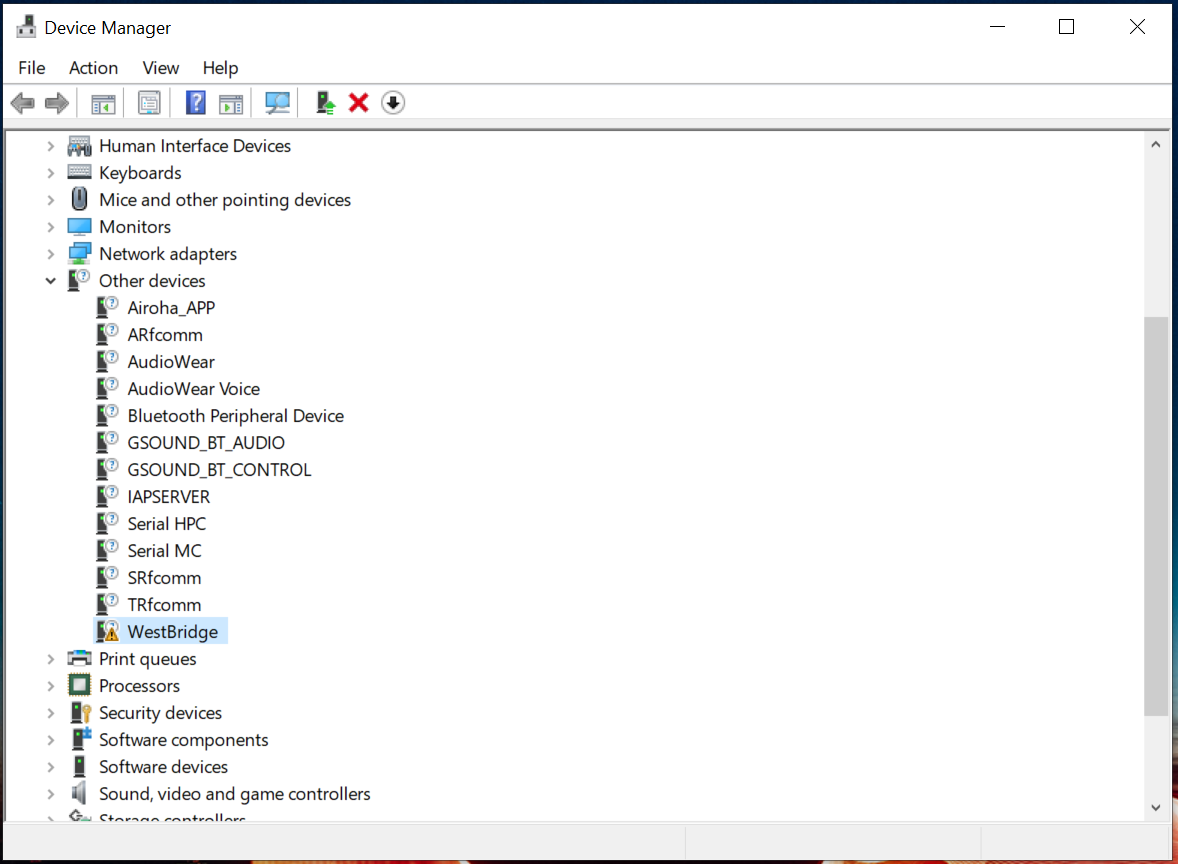
Please connect the kit by USB, and then open Device Manager to confirm that there is a device named "WestBridge" displayed.
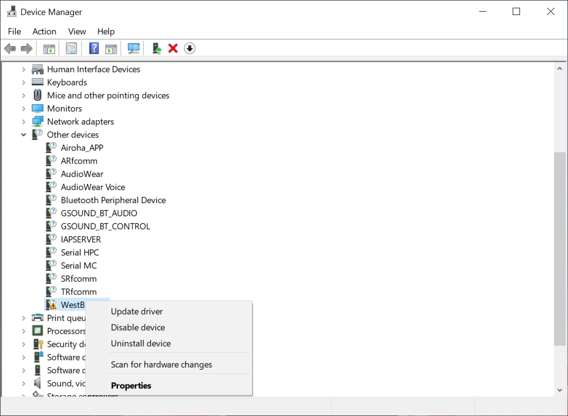
Step 3: Select "Update Driver(P)"#
Please select WestBridge, right-click and select "Update Driver(P)".
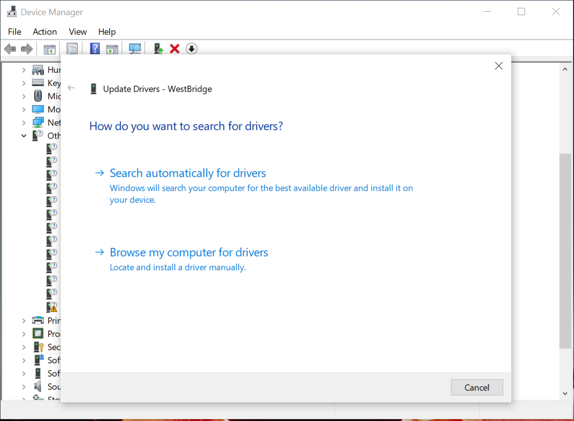
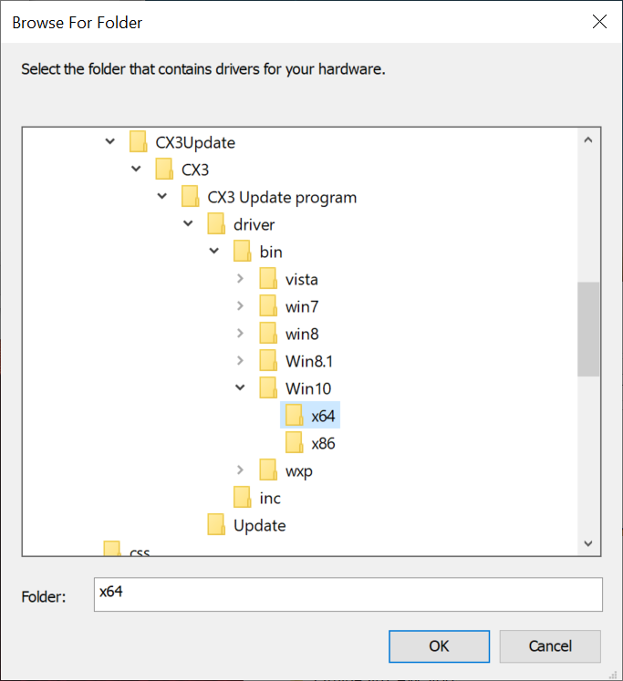
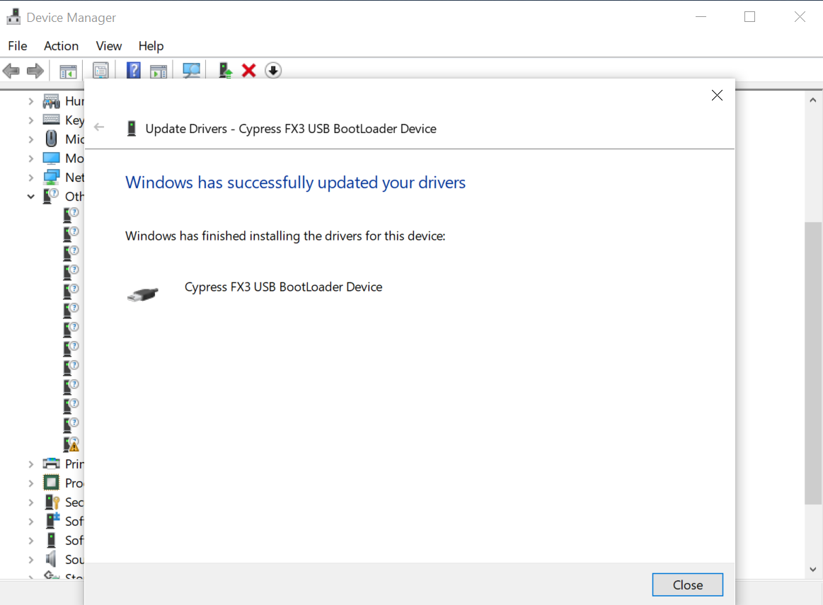
Step 4: Browse the driver in computer#
Select "Browse my computer for driver software". Then select the driver file that corresponds to the operating system you are using. If "The driver has been updated successfully" appears, the installation is complete.

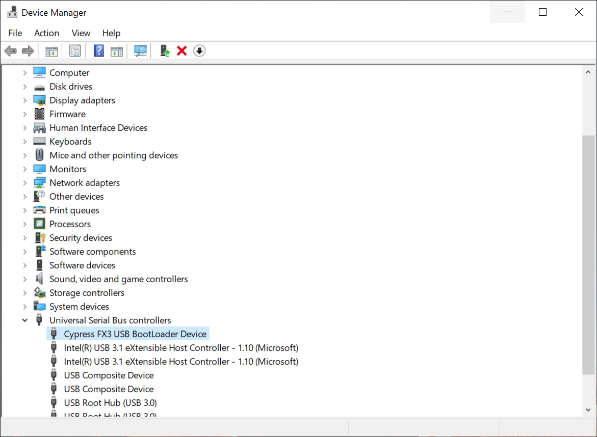
Step 5: Reset conversion kit#
Press the Reset button or reset by disconnecting and reconnecting the USB to reset. Then, check that the Cypress FX3 USB BootLoader Device is displayed under Universal Serial Bus controllers. If it is displayed, the preparation is complete.
Write firmware#
Step 1: FW update mode selection#
Mode switch to right side for "FW update mode"
Step 2: Connect the device#
Plug in USB port, and Device manager list shows a new device "Cypress FX3 USB BootLoader".

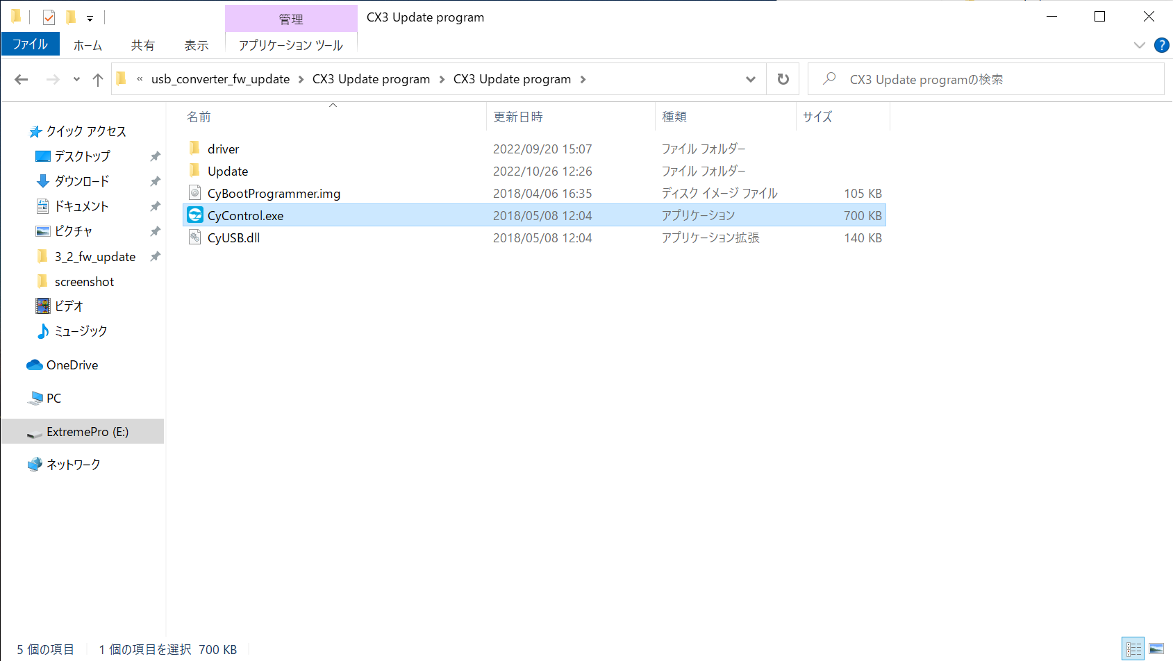
Step 3: Open a UpdateProgram directory, and start FW update tool#
Extract a UpdateProgram and Open the Update Program directory. Then, Execute CyControl.exe.
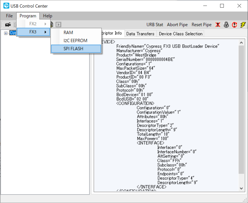
Step 4: Select a SPI Flash#
Select a SPI_Flash in the menu(Program > FX3 > SPI_FLASH).
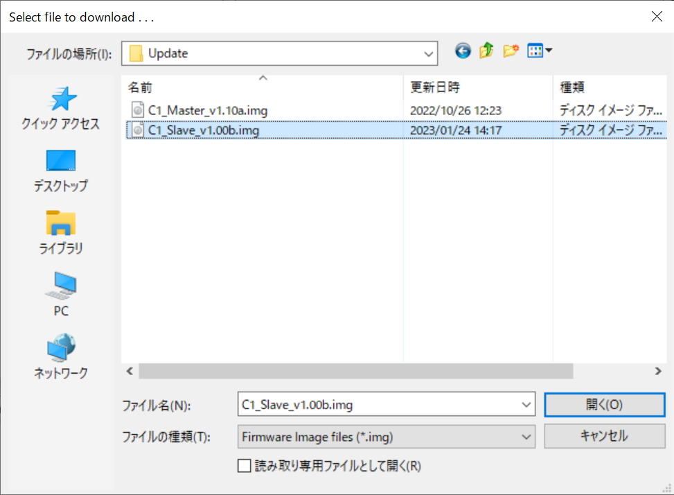
Step 5: Select a Image file#
Select the file corresponding to the mode you want to use
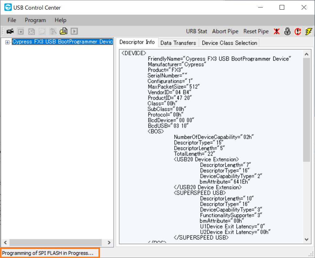
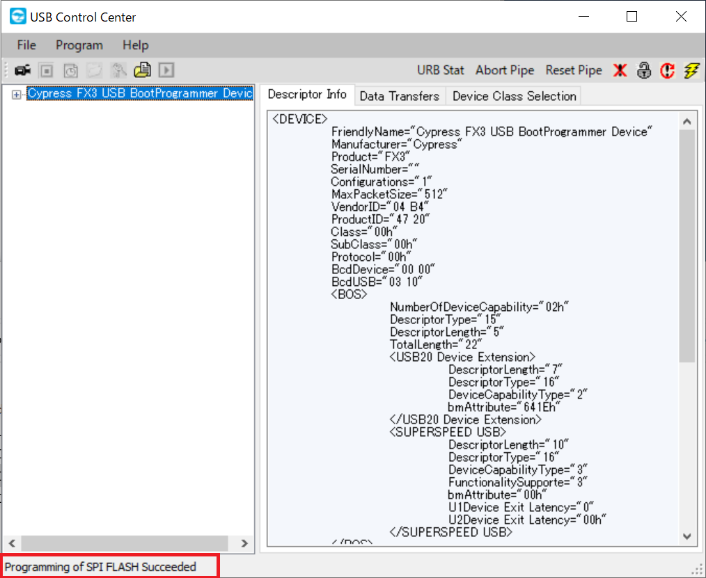
Step 6: Wait for programming succeeded#
Please wait until the display changes from "Programming of SPI_FLASH in Progress..." to "Programming of SPI_FLASH Succeeded."
!!! warning Please do not remove the cable or turn off the power while writing.
Step 7: Reset conversion kit#
Slide the ModeSwitch of the USB Conversion kit to the left (Normal Operation) and press the reset switch.
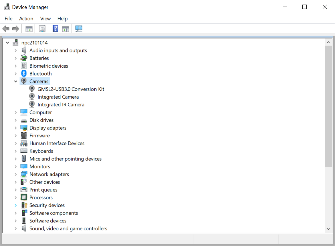
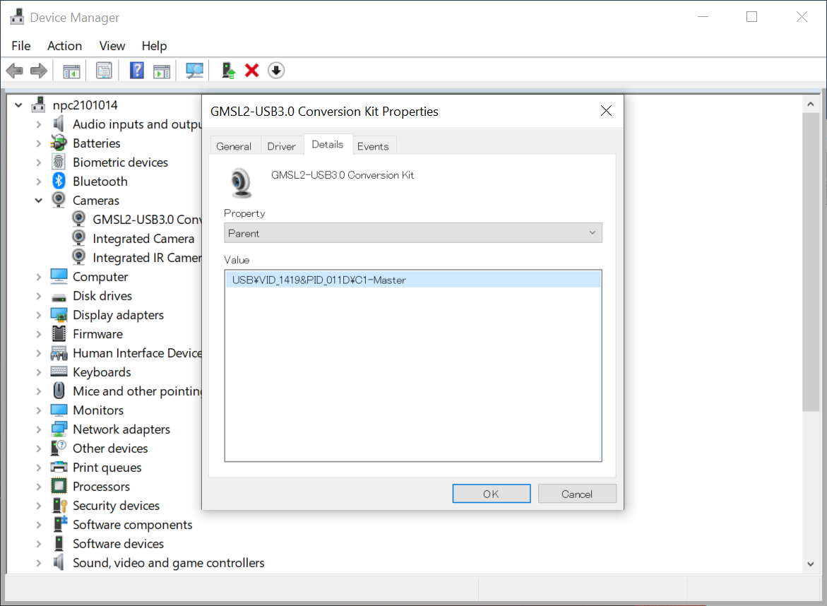
Step 8: Check the firmware version#
Please confirm that the "GMSL2-USB3.0 Conversion Kit" is in the "Camera" of the Device Manager. Also, you can confirm that the mode has been changed by checking the properties of the device. The mode change is now complete.